Saturday, May 27, 2017

Improvement to False Rib Forming Tool


 I'm working on making a set of False Nose Ribs for the Hogan's WACO TEN project.  One of the things I discovered was that the bearings in the roller had worn out after about 600 pieces were made.  Back to Tractor Supply for some cheap new bearings.

 I also realized I could eliminate clamping the leading edge of the rib.  by changing the length of the small steel clamp which holds the tab in the slot, preventing the aluminum strip from sliding while forming, I can use it to replace the plastic clamp.
 
 The small tab was made just to hold the tab in the slot.  I made a new one which extends about 3/16" onto the formed rib.  At that point in the forming process the roller is pushing the ends down to start the form so the clamp is not in the way of the roller and I don't need to fool with an extra clamp, which was always sliding off anyway.

The clamp only touches the rib at the tip of the clamp.


1 min 23 sec video of rib forming.  The Blog software degrades the quality.


Thursday, March 16, 2017

New Fittings Done - Big Mistake


 I have all the new set of fittings, formed, welded and painted.  Unfortunately I have to remake all the welded fittings.  I left the holes to be drilled to final size after welding just to be sure the holes were well aligned even if the fittings moved slightly while welding.  It also allowed me to use 3/16" and 1/4" screws to hold the fittings while welding instead of a bunch of different sizes.  It all worked the first time when I remembered what I was doing.
 The 2 bolt holes along the bottom of the fittings should be drilled so the inboard hole is 1/4" and the outboard hole, in line with the brace wires, should be 0.377" (letter V drill).  Instead I reversed them. When I made the first set of fittings, I made the template with the inboard hole 1/4" and the outboard hole 3/16".  The assumption was that I would only drill the outboard hole.  I should have looked carefully at the drawing and I would not have made the mistake.  Instead I thought the bigger hole get's the bigger drill, etc.  I'm making new parts.
To make sure I don't make this mistake again I've made new templates.  I've stamped the finished hole sizes on the templates and reversed the size of the 2 problem holes.

This is so annoying.  I was ready to start sawing the wing spars.

Friday, March 10, 2017

Band Saw Blade Brazing and Folding

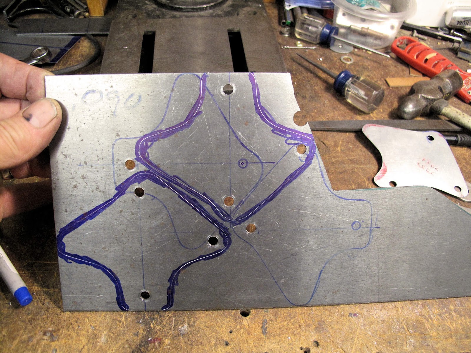
I gave a presentation on making fittings at our last EAA Chapter meeting.  One question asked was how long the braze joint on the blades lasts, and how much extra length I leave in the blade for re-brazing when the joint breaks.  I was speechless.  I've never had one break to even think about it in years.  I braze them, cut metal until the blade is dull, and put on a new blade.  All the fittings I just made for the wings were cut with one blade. All those pieces were 0.090" or 0.187" thick normalized 4130.

I made my own fixtures for forming and brazing the joint with blade stock I buy from McMaster-Carr.  I've gone through a few coils of blade stock over the years.  I'm not always careful with what I try to cut so I've ruined a few blades.

The metal cutting blade stock I buy is 1/4" wide by 0.025" thick with 18 teeth per inch.  It comes in coils 100 feet long.

For the Sears band saw the blades are 80" long.  While putting this together I messes up a joint trying to build up too much braze material to show grinding it off.  I ground too far and weekend the blade.  When I cut out the joint and re-brazed it I discovered it was too short to fit on the saw wheels.  There seems to be enough adjustment for 1-2" longer blades.  In the future I'll make my blades at least an inch longer.  You don't want it so long you can't get it tight.

All of this involves operations which are why I wear safety glasses 24-7, protect your eyes.

I have marks on my shop floor and just cut them to length with snips.  If I don't cut it square I lightly square up the end on the belt sander.

The first step is to grind a bevel on the ends of the blade.  I made this fixture from a scrap piece of plywood.  The angle recommended gives a 3/32" wide ground flat on a 1/32" thick blade, which from the arc sine is about 19.5 degrees, 3/32" hypotenuse and 1/32" opposite side.  Math is so much fun!

The slot for the saw blade keeps the teeth off the wood so the blade sets flat in the groove and square to the side.

The screw studs have a wood screw end with a 10-24 thread on the exposed end.  You need the lower screw as close as possible to the blade end, but far enough back so it doesn't touch the belt on the sander.

You grind one end of the blade at a time using the same groove and they fit together perfectly.


I use the belt sander on the Shop Smith.  Set the table and the miter square to the belt.

Hold the fixture against the miter and gently grind the end.

After grinding each end should come to a point and the ground end should be square and even, so the ends fit together well.


The original little brazing fixture I bought didn't hold the 2 ends aligned well.  I made a fixture from a 24" piece of 1" x 1/8" angle and a 2" wide strip of galvanized steel.  The angle gives it some structure and the galvanized piece is the straight edge to assure the joint keeps the blade straight.  If you cut this piece with snips use the factory edge for your straight edge.  I believe this could all be as short as 12" and still work very well.

The overhanging edge of the galvanized steel gives me something to clamp on the edge of the bandsaw table while brazing, so I would make the length to easily clamp on the saw table.

To hold the blade down I used some aluminum sink clamps.  The screws have a nut under the clamp to hold the galvanized on the angle.  The wing nuts tighten the clamps on the blade.  The galvanized is positioned so the teeth of the blade are off the edge of the angle, again so the blade lays flat.

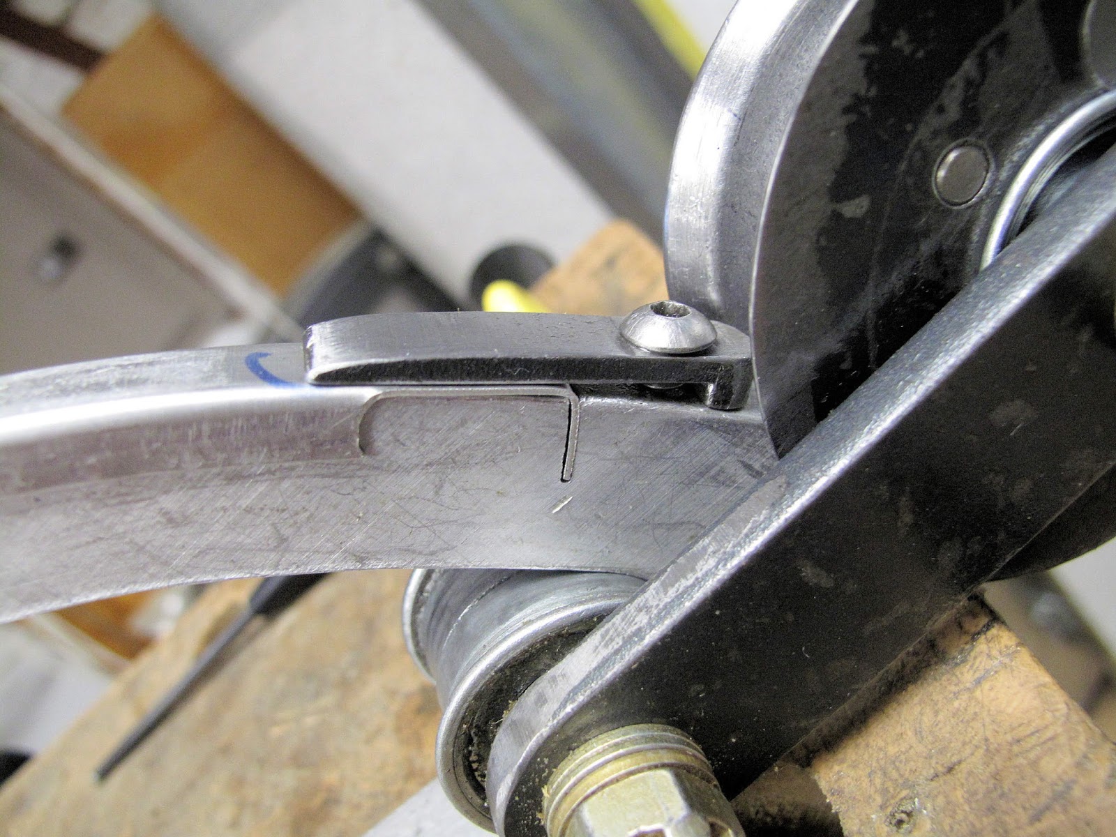
The first end of the blade is clamped with the end in the center of the notch which gives clearance for brazing.  Make sure the back edge is tight to the galvanized straight edge.

The second end is positioned so you can see a bit of lower bevel, and the back edges are in a line.  You don't want them to overlap in a way that the joint is thicker than the blade.  Some times the 2 bevels don't touch each other.  Gently bend the first end up very slightly so the 2 bevels are just touching.  If they aren't touching you can get a thick joint.  A well made joint won't clunk going through the metal when sawing.


The blade is in the fixture which is clamped to the bandsaw table ready to braze the joint.

It's easy to overheat the blade when brazing.  Use a tiny jewelers torch to prevent overheating.  I found this cheap Butane torch for a couple dollars.  I think it was at Tractor Supply.  The problem I've had with them is they leak so they loose the charge quickly and they don't hold much.  There are suggestions on-line for how to improve them.

Hold the filler end of the torch up and press the can of Butane down for 10-15 seconds to fill the torch.  The instructions say to let the butane stabilize for 5 minutes before using.  These cheapies leak so badly I don't wait.  It's annoying to have the flame die just as you're about to add the brazing wire.

You need a brazing flux.  It's mixed with very little water.  It works best when it's a stiff paste.  All you need is a dab bigger than the head of a pin and smaller than a BB.  Force it in the joint and make sure it covers all the ground surfaces.  Also make sure a thin layer is applied about 1/4" beyond the joint on all sides.

The silver brazing rod which works best is Cadmium free and made of Ag - 50%, Zn - 28%, Cu - 20%, Ni - 2%, which is the mix of this Harris wire.  One troy ounce will probably last until I'm 300 years old so I shouldn't need to buy any more.  I would have preferred a 1/32" wire or even finer so it melts easily.  You need an amount about the size of the head of a pin to make the joint.  It melts between 1220 and 1305 degrees F.

As you start brazing the water in the flux bubbles of at 212 degrees.  At 600 degrees the flux becomes white and slightly puffy - like fried eggs.  At 800 degrees the flux smooths out.  At 1100 degrees it becomes clear.


Shortly after that the blade starts turning dull red.  Part of why you need the blades touching is so you can get both ends hot enough to allow the brazing material to flow into the joint.

Just like soldering, you want the heat of the blade to melt the braze material,not the flame, so you don't get a cold joint.  I found the wire worked better if I hammered it thin so it would melt and flow into the joint easier.

You should see a little on the back side of the blade where it flowed through the joint.


Everything needed to braze a blade.
If you get a little extra brazing material on the blade you can lightly grind it off.  The Dremel tool works well.  You can also bend the blade and touch the flat area, not the teeth, on a grinding wheel or the belt sander.

Time to get sawing.  I usually make a few blades while I'm doing this so you need to learn to fold bandsaw blades, keep reading.

To fold the blade hold one side of the loop by you.  Hold the other side of the loop with your finger tips and thumb.  You're going to twist the bottom edge of the far side toward you.  As you twist the ends will start to bend upwards.

Always have the joint in a blade on the side away from you just in case it fails.  The ends will go out away from your face.

As the blade is twisted to 90 degrees the ends of the loop have folded down to about 90 degrees.

As you get to 180 degrees the 3 loops are formed which lay onto each other.  I always put a small zip tie around one side of the folded loops to make sure they don't accidentally unfold.  A sharp wood cutting blade can give you some nasty cuts if it accidentally unfolds.


A short video.  This is so easy once you get it.

Thursday, March 2, 2017

Improvement To Wing Fitting Weld Fixtures


 When I welded the original set of wing fittings I had trouble keeping the guide plate, for the strut fitting, centered between the spar fittings.  I realized I could use some cheap washers stacked on 2 of the spacer bushings to hold the plate loosely in the center.  A fist full of washers at Tractor Supply is about 50 cents.

I stacked enough washers on 2 of the spacer bushing then installed the guide plate and finished with more washers.

The washer stack needs to be a little shorter than the bushing, so the bushing does the spacing.


 The other fitting goes on and the nuts get tightened.

The strut fitting sets in the guide plate.

Four fittings ready to weld and the guide plate doesn't move around.

Thursday, February 16, 2017

Making Accurate Fitting Blanks

While writing the last post on wing fittings I tried linking it to an older post on making the fitting blanks.  I discovered I never wrote it so this posting is intended to explain the process I use to make accurate blanks.  The older posts on the wing fittings start with the process of bending tabs on the fittings and go on to welding and painting.

This post is focused on making the unbent blanks with holes accurately located so parts are interchangeable in the various locations where they get installed.  On our Fly Baby we drew each fitting on the steel sheets, center punched the holes and drilled them.  The hole locations vary enough that each part only fits one location on the plane.  If you take them off and don't get them back in the correct location things don't fit together.

In 1970 I learned Matched Hole construction while stationed in Japan.  Two guys in our EAA chapter at Tachikawa Air Base, Al and John, were building Thorp T-18s. The planes were made of riveted aluminum and all the rivet holes were pre-punched, by them, and when they had made all the parts they assembled them and riveted the planes together in 2 weeks.  All ribs, skins, etc. had the holes pre-punched, by hand, and were completely interchangeable.  Since then I use matched hole techniques for everything I make.  It turns out it's easier and faster than laying out and drilling parts by hand.

I make templates for each part from galvanized steel.  The steel holds up well, it's cheap, and is dimensionally stable.  Most hardware stores, etc. have 24 gauge (.028") galvanized steel sheet. One of the nice things with making a template is that you can make mistakes and remake the template very cheaply until you are happy with it.  Much better than wasting expensive 4130 steel.

The templates are first used to lay out the needed parts on the steel, or aluminum, that the parts will be made from.  On steel you can use pencil, but it corrodes aluminum.  Don't scribe the edge at this point.  I find Ultra Fine Point permanent markers work great.  If you don't like what you did just wipe it off with MEK, etc.  You need to leave 1/16" between parts on straight runs and more at inside corners so the saw blade can make the turn.  A 1/4" band saw blade needs at least 1/2" to 3/4" radius to cut a corner.
Once the parts are drawn on the sheet of steel, center punch one hole at one end or corner of the part.  You want this punch mark as close to the center of the hole as you can so the finished part will be located where you drew it on the steel.  If you mark it too far off center you may not be able to saw out the part after all the holes are drilled.


I use an automatic prick punch (on right) to mark the center and then use a center punch (on left) to give the mark a shape which the drill will center on better.  The point on the automatic punch is more pointed, so it makes a deep mark, and is easy to locate because you can see where you are placing the point better than a center punch.

The angle on the tip of the center punch matches the angle on the drill bit so the drill will center on the mark better.  I know it's an extra step but it's worth it to get more accurate holes.  If you're using a Whitney punch in thin steel or in aluminum the prick punch is all you need, not so for drilling.
Drilling holes in fittings I normally use center drills.  They are short so they flex less than standard twist drills.  They also have a pilot to help keep the hole from wandering.  Cutting oil is always a good idea to make your drills last longer, but it is messy.
After drilling each hole I deburr the hole.  If the burr is large I file it with a mill file then use the deburring tool.  Getting rid of the burr after each hole helps the metal set flat while drilling, and it has to be done at some point before painting.  I like my Vargus Shaviv tool.  They have a variety of tips for it and they sell parts.  If you use it enough it will eventually wear out.


Once the first hole is drilled the second hole needs to be center punched and drill.  I like my first 2 holes to be as far apart as possible to help give better accuracy to the remaining holes.  I have duplicating punches for center punching holes but for thin templates and such I prefer to just use the punches for my Whitney punch.  The Whitney punches have a shorter centering nib than the duplicating punches.  Since the holes in the templates were made with the Whitney punch, their punches fit more snugly in the holes.  Because the template is so thin, you need some spacers to hold it up from the part while punching to keep the punch in the template.  I normally just use washers a spacers which is why I like the shorter nib.

Put a bolt in the first hole to locate the template.  Then line up the template with the lines on the metal, with the punch in the second hole.  A quick rap with the hammer and you have a nice mark ready for the center punch to finish it.

With the second hole marked for all the parts it's back to the drillpress and then deburr the holes.

With 2 holes drilled, bolts go in both holes and the rest of the holes can be center punched, drilled and deburred by the same process.
After all the holes are drilled, check to make sure bolts go in all the holes of the template and the part.  If the holes are drilled correctly, draw a wide line, with a felt marker, covering the edge of the cut line.  Carefully scribe, through this wide line, around the edge of the template.  You don't want to ruin an adjoining part with a slip of the scribe.

Drilling the holes in this way gets the holes located within a couple thousandths of an inch.  WACO generally reamed holes 1/64" oversize, which gives very interchangeable parts.  I ream hole oversize after bending and welding so the holes are still a snug fit for locating in the forming and welding operations.


Some times even with the best efforts the holes don't line up with the template, "X"ed out below, or like the parts at the right which I drew with the bends parallel to the grain of the steel.  Bends should be made perpendicular to the grain for best results.  Because I hadn't scribed the parts until after drilling the holes I was able to use the steel.  If it were scribed first it would have gone in the recycle bin.  I also don't waste time cutting parts with poorly located holes.

Grind edges smooth and straight on the belt sander (60 or 80 grit belts), much easier than filing.  Some areas may still have to be filed but I use the sander whenever possible.

Also a bolt sticking through a block of wood makes a nice pivot for grinding very smooth even radii on parts

 I found the disc sander works well to get at some inside edges.  Also a 1/2" bandfile belt sander works well in some areas.
 
  I lightly grind the edges, perpendicular to the shaping grind, to smooth off any grind marks.  It also helps you see if there are saw cut marks which need to be cleaned up.  The little bandfile held in a vise works well for this also.  The last thing is to file off the remaining fine burr along the ground edges.
Lots of parts ready for bending and welding.  Making stuff is so cool.  It's even more fun when parts are well made and completely interchangeable.