Before we start I added some notes to the end of the wire Straightening post.
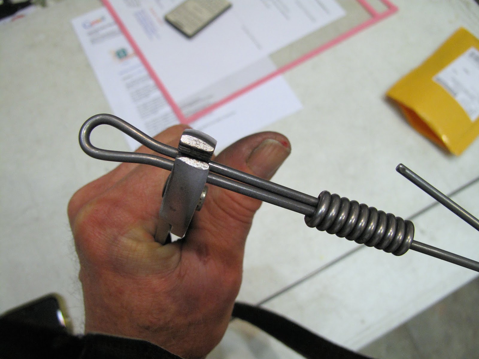
I need to bend this hair pin looking bend on both ends of each drag wire. One end gets a turnbuckle and the other gets a Wire Clip (attachment fitting). The free end gets squeezed closed, a ferrule slipped on tight, and the end of the wire bent over to lock it together.
We're doing this on each end of a piece of 1/8" piano wire about 5 feet long.
I did something similar for wire wrapped cable bracing so I thought I'd build on that idea rather than build the more complicated WWI wire bender, for which I have drawings.
The bends are the same on the 1/8" 1x19 cable. The cable is easier to bend, but it springs back more . When finished they both have the same shape.
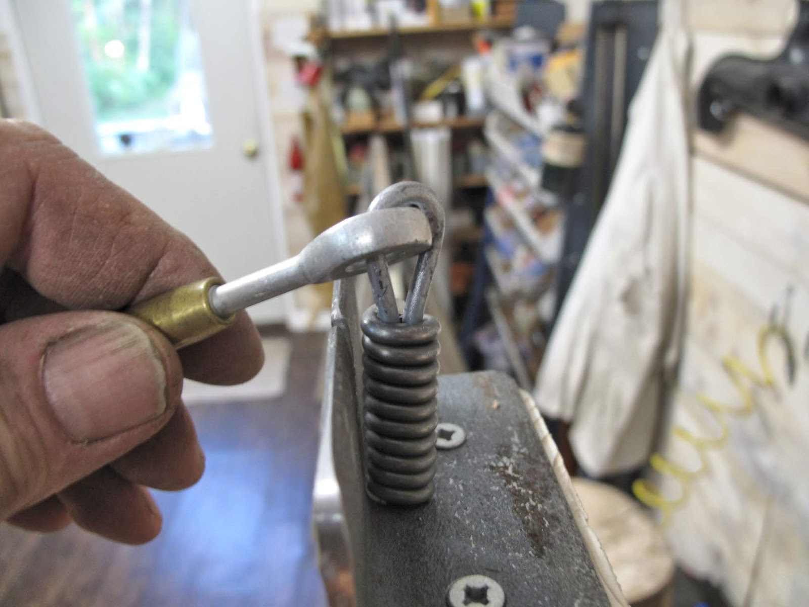
I bent the cable with battery terminals. They have the perfect shape for forming the cable bends. They also keep the cable trapped in the groove while bending.
They're made of brass which is not hard enough for bending our piano wire so I can't just use this bender
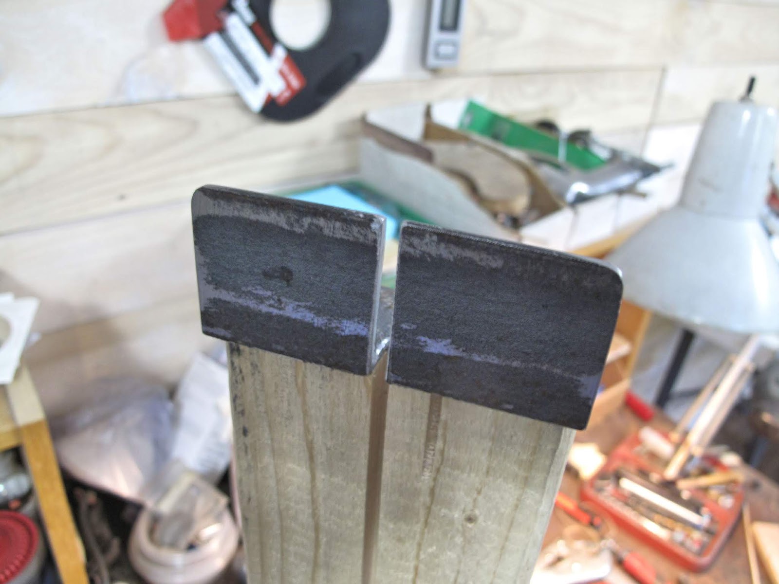
First I made some posts to bend the wire around. They're made from a 3/16" AN bolt, 2 washers, and a short piece (5/32") of 5/16" x 0.058" wall thickness 4130 tubing.
I ground the end of the tube square, cut off a piece slightly too long, then ground the cut end square and to length. To hold them while grinding I used a longer piece of the same tubing with a piece of 3/16" rod inside. I left the end sticking out 1/8", put the short piece on it, and ground it down very gently while rolling it to keep it square. It works real good. Being careful you can control the length to 0.0005".
Four bushings.
I didn't have a completely clear idea where I was going when I started, so I built this as I did each step in the first piece I bent. Surprisingly it works very well.
I use the Dremel tool to cut off the wire. I like the new quick change wheels much better than the old ones.
I blunted the ends of the wire so it will slide into the ferrules easier after all the bending.
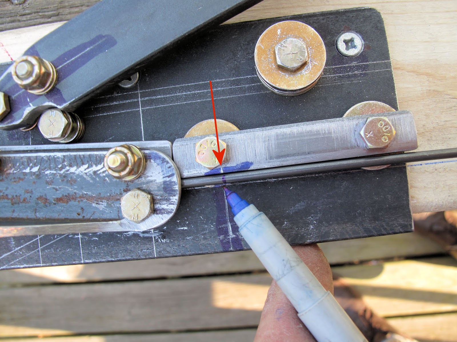
An allowance of 5 1/2" from my bend reference line gets just the length I want to bend over the ferrule at the end. I mark it with a Sharpie. We use this mark for the first 2 bends. The mark is not at the bend which is hidden under the lever.
The base of the bending fixture is a piece of 3" x 2" x 3/16" angle iron. For this First bend I'm using one of the posts at the pivot of the arm. I have a piece of 1/8" steel to back up the bend on both sides of the post. It helps get a sharper bend. Without it the wire on both sides of the post tend to be curved a little and here I want them both straight.
You can see from the side how I had to use washers to get clearance for the bolt heads.
Below is the backing bar on the bottom of the lever.
The first bend is made by eye, over bending slightly, so the wire springs back to the bend line. The lever is rotated anti-clockwise to make the bend.
The finished bend is 15 degrees.
For the next loop bends there are 3 of the bending posts. One is at the pivot of the lever. The other 2 are 5/8" away, one attached to the bottom of the lever and the other on the base. The reference line gets the wire in the same position relative to the bend post as in the first bend.
I found I need to use a pair of pliers to grip the wire to keep it from moving. The pliers have been modified so they won't scratch the wire. More on them at the end of this post. They're really part of making that locking bend around the ferrule. The stack of washers keep the pliers from moving.
The lever is rotated Clockwise until the wires touch. This leave the 2 sides of the loop parallel.
With a 5 foot piece of wire I had to do this on my deck outside the attic workshop. The end of the wire is actually resting on the far railing. Life works out some times.
The wire goes back into the fixture so the free end goes from the left of the fixed post, past the right side of the pivot post, then to the left of the post under the lever. The wedge of scrap spruce keeps the loop tight to the fixed post.
The lever is rotated anti-clockwise, over-bending slightly, so the wire springs back to the red line. The finished bend on this side is also 15 degrees.
The 2 sides are still parallel but it's looking more like our hairpin bend.
Back into the fixture like it was for the 2nd bend to add a few more degrees of bend to the loop. The idea is that when the loop is closed, when the ferrule is installed, the free end is snug to and parallel with the main wire. That's why I didn't want any bending of the main wire when I formed the first bend.
We have our finished hairpin bend.
That takes care of the loop at the first end. The second end is almost the same process.
To make the second loop I've added a 6 foot piece of 2x4. I pounded the back of the fixture onto the board, with a soft mallet, so it would mark where I needed 1/2" holes for the bolts and nuts. The fixture is screwed to the board.
A c-clamp holds the board to the railing of the deck while doing the bending.
It turns out that one of the few accurate things on the old drawings is the length of these wires. The board allows a place for stops to control the length of each cable. For stops I used 16d finishing nails cut 2" long and re-pointed on the belt sander. I positioned them so they can all be permanently installed and each wire clears. The first bend is offset 1 inch to the right of the 2nd bend so there are 2 sets of stops, offset by 1 inch. There are 2 wires which are shorter then 2 other wires by 1/8" and by 1/4". Rather than clutter the fixture with more pins I have notes to open the turnbuckle 1/8" and 1/4" when making those wires. Ok, I know that's not fool proof so let's hope I can focus long enough not to screw it up.
The first step for the second end is to loosely attach a turn buckle, slide on 2 ferrules, then start one ferrule onto the free end to hold it shut. I have a reason for not finishing this, we'll get to it in a later posting.
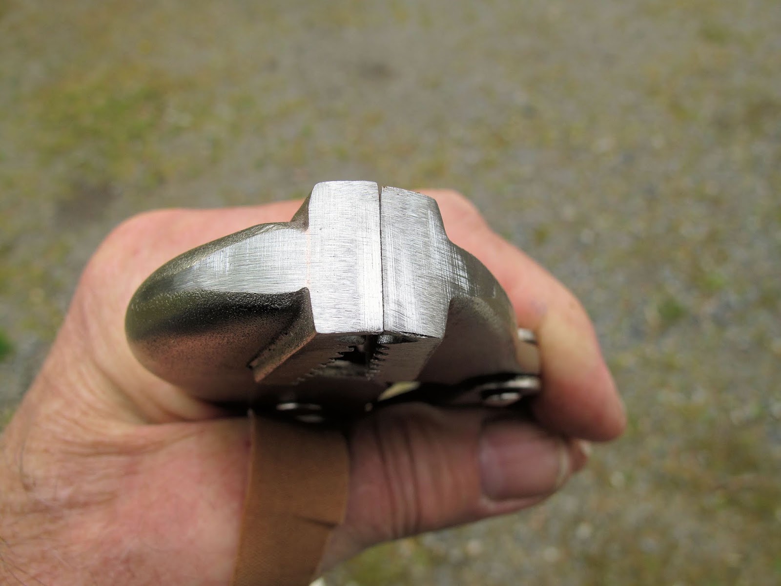
I had to modify a pair of pliers to squeeze the wire without scratching it.
I filed a pocket in each side with a 5/32" chainsaw file, then rounded the corner with it. We don't want these wires cracking from some scratch.
The pocket holds the wires together to slide the ferrule on. You can't push them all the way on like this so I'll need another tool for that, later.
I adjust the turnbuckle to have the threads just at the ends of the barrel. The wire is positioned in the fixture as if to make the first bend, with the turnbuckle on the appropriate pin.
The reference mark is made on the wire. The wire is removed and positioned so the mark is on the line. The wire is then marked to cut off the excess, leaving 5 1/2" form the mark.
The end is again blunted. The second end of the wire is now bent as before. The clamping pliers are not needed because the turnbuckle end is held by the pin. After the second bend is made you need to loosen the turnbuckle to get the wire out for the 3rd bend.
With the both ends formed, the wire clips were loosely installed and the wires bolted into position to verify the length. The length was a fit perfect, well done WACO draftsman.
All the wires are formed for both lower wings.
On to the upper wing wires.
The visegrip pliers were modified to be able to grip the free end sticking out of the ferrule and bend it most of the way around.
I used the Dremel cut off disk to grind a more round hole in the tip of the pliers.
Then I filed the corners round to prevent scratches.
The tip of the pliers was then ground off on the belt sander. Keep in mind I'm trying to grasp a wire end setting very tightly against the main wire. I can always grind it down more if needed.