The ailerons on the NINE are cable operated. This bracket holds the bracket with the aileron pulleys in the lower wing. The pulley holder pivots on this bracket. The cables run along the front side of the rear spar from the control stick to the pulleys and from there up to the aileron. The bracket mounts on the front face of the spar. The pulleys are mounted above this and parallel to the spar.
The plate # 7035 goes on the aft side of the spar because the lower bolt is actually below the spar. The factory glued on a little block of wood but the load is carried through this plate. Because of the odd shape and lack of a flat layout on the drawing I suspect this is another part they bought as war surplus and modified to fit by grinding off one side. You can see the 2 bolt holes in the rear spar just to the left (inboard) of the strut fitting.


Like all the steel parts I make, I start with a galvanized template. The material is cheap and if you mess up just bin it and make another one. To make the actual parts I start by using the template to center punch and drill the holes in the sheet of steel, then scribe the cut lines when I'm sure the holes match the template. If the finished holes don't match the template I can often use the steel for some smaller part if the lines haven't been scribed or cut. This method is of locating the holes is so accurate I can usually stack up a half dozen or more parts and put bolts through all the holes. The parts are cut out on the band saw and the edges ground to the line with the belt sander and drum sanders. I always round corners and deburr every edge. Sharp corners add weight, sharp edges don't hold paint and they draw blood.

I need a form block to bend the part into a U-shape. I'm cutting it from 1/2" thick bar stock with a 5 degree angle to allow for spring back. For steel this thick (.090") the block needs to be 11/16" wide to get a part with 3/4" between the legs. The block is 4" long so cutting oil is important to protect the blade from overheating. It also cuts faster with the oil. I had just brazed up a new blade so the cuts were done before the Patsy Cline album album on my i-pod. Noise cancelling earphones are a must.
With the sides cut to a fairly straight line at 5 degrees, the next step is to grind the sides smooth with the belt sander. The part quickly gets too hot to hold so I cool it regularly by setting it on the end of my vacuum cleaner hose. The fast moving air cools it nicely. If you cup your hand over it to form a tunnel it cools even faster.
After grinding it smooth, if you very lightly grind perpendicular to the grinding you leave a very smooth finish.
Next the first hole is located and drilled. In thick metal I start the hole with a center drill and finish drilling through with a regular twist drill. The hole location is much easier to control with the center drill. The other trick is to mark the hole location with a prick punch and then improve it with a center center punch so the drill centers in it better.
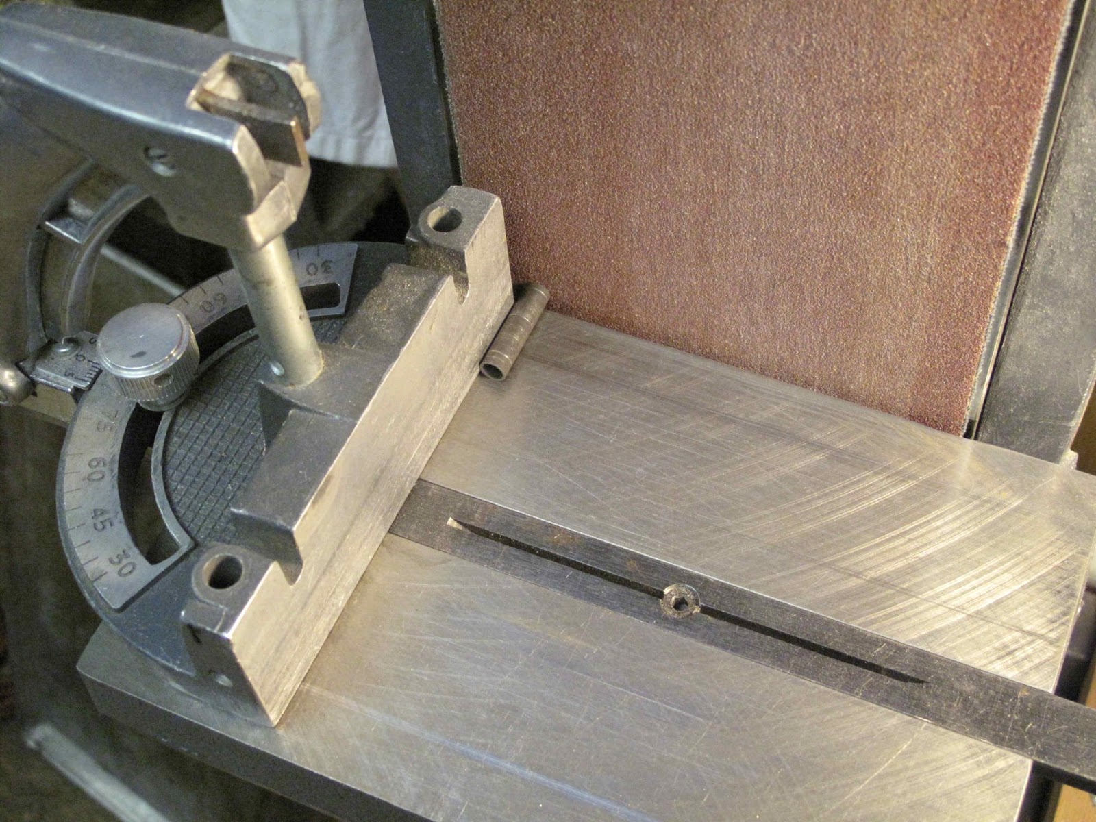
The second hole is duplicate punched using the part template to assure the holes line up with the parts when clamping everything with bolts.
The holes are drilled and the sides ground. The drawing doesn't specify a bend radius so I used a 1/16" radius on the 2 corners. I ground and filed the corners until they nicely fit my 1/6" radius gauge.
I made the backing block slightly off center so I could hammer close to the bend because of the .090"steel I'm bending.
I made the backing block slightly off center so I could hammer close to the bend because of the .090"steel I'm bending.
It all seemed like a good idea but I couldn't keep it in the vise when I pounded on the part to bend it. It worked fine when I clamped it in the side of the vice, but there was no way to clamp it and bend the second side.
Back to the drawing board. I made a longer backing block from 2 pieces of 3/16" steel left over from making the
form tool for the false nose ribs. I probably could have used one piece of steel but you have to pound so hard on such a wide bend that I felt better with 2 pieces. I didn't want it to bend instead of the part. The part and blocks are assembled the same as the first one.
It all clamps in the vice much better and it was easier to hammer on the top of the vice. There is a work piece protector on the jaw of the vice to keep the bracket from getting scratched.
The part is now re-clamped in the blocks to form the second bend. Which now can be easily done on the top of the vice just like the first bend.
It came out great. Because there is a right and a left part you just have to pay attention to reverse the blank before making the first bend.
With the part bent the hole in the second leg can be drilled. Because the legs are close enough together I started the hole with a center drill. It doesn't accidentally enlarge the first hole. The center drill is too short to make it all the way through so I finished it with a regular twist drill.
The parts are ready to paint. I probably should make the pulley holder while my brain is on the subject.