The stabilizer is missing from this project so there is no choice but to build a new one. I do have the factory drawing, the drawing the Air Corp made of their NINE and the stress analysis. When I built the jig for the elevators I made it so I could use it to build the stabilizer. The only problem is you have to tack weld 1/2 of it then flip it over and add the parts for the other half. The first step is to form the leading edge. It's made from a piece of 1/2" x .028" tubing.
Waco originally used 1005 steel, then 1010 steel and by the time most of the drawings were last revised they were using 1025 steel. Today I'm using 4130 steel because that's what is readily available in a seamless tubing and it is stronger. The disadvantage of 4130 is that it is an air hardened steel which means it will cool fast enough in the air to harden it. Even a slight breeze will cool it fast enough to harden it more than desired. It's easy to get it hard enough to make it brittle. Low carbon steel, like 1025, doesn't have this problem but it is weaker than 4130 so you can design a lighter structure with 4130, which is why we use it today. I have no desire to re-engineer the plane so I'm just using the same sizes of steel originally used .
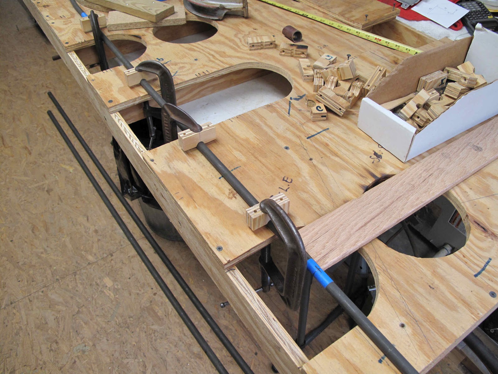
I made this piece of tubing 14'-6" long. That's longer than needed but I needed enough extra at each end to be able to easily form the bends. I think you could still do this with a piece 14'-0" long. I started with the center of the tube (mark on blue tape) at the center of the stabilizer. The blocks clamping the tube to the lines on the jig are the standoff blocks, turned upside down, I made for holding the tubes in place. The blocks were made so the centers of the spars and leading edge are on the same plane, far enough from the board so the bottom ribs can fit under the spars.
I used the same curved board I made for bending the trailing edge on the elevators and clamped it to the jig to form the bends at the tips. I found it made a nice smooth curve by moving the board in about 1" increments. In 2" increments you can see straight sections between the bends.
I could have used more holes in the jig to hold the tube in place as the bend progressed.
As an alternative I clamped some blocks to hold the tube from over bending as I moved along the tube.
At the end of the bend I had about 8" of tubing to cut off at the back of the spar (blue tape).
The second bend was made with the same process. The trick was to line up the first bend, dangling past the end of the board, with the surface of the board. By clamping the jig to the table so it would stand on edge I positioned the bent end parallel to the board. It took several tries because the clamp needs to be exactly over the tube as you tighten it or the block rolls and the tube rolls with it.
In the end both ends are bent and lined up.
The next step is to make the spar tubes.
Sunday, May 20, 2012
Nose Cowl - P/N 7016
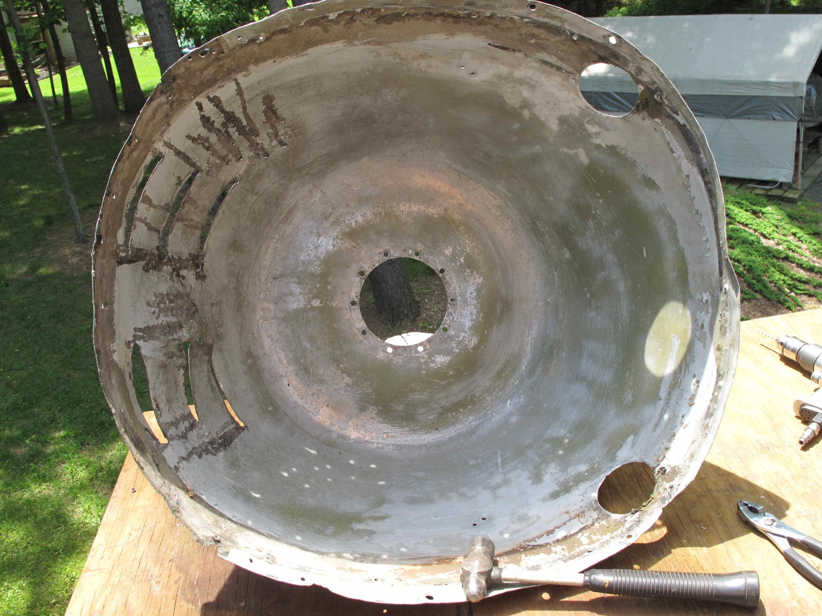
I've learned to gas weld aluminum while working on my Cessna 140 project so I decided now was a good time to work on repairing the nose cowl. It's in pretty bad shape. Someone has cut holes in the top and louvers in t he bottom. The outer shell (P/N 7018) is spun from .040" soft aluminum. The cost of getting a form made and having someone spin such a large piece (25" dia. x 12" deep) is beyond my budget. Making one without spinning it would require forming sections and welding them together so fixing this one seems a better plan.
The stiffness of the cowl is created with a former (Collar P/N 7019) which is formed from 1/2 hard .032" aluminum.
The first step is to strip the paint so I can work on the bare aluminum. I've tried several strippers and I think I've found one I like. It's Zip-Strip Contractor Plus paint and finish remover. It has all the nasty stuff in it that makes a good stripper work and it washes off with water very nicely.
With the paint and bondo removed it's obvious the plane this was on went on it's nose. The cowl was roughly hammered out and it's pretty rough.
The top is in very good condition. The holes will be easy to fill and there is a little wear where the belt buckle rubbed. The cowl is all held shut with a leather belt and metal buckle. Because the top is so good the worst I'll have to do is cut out all the bottom and replace it. That's still better than making the whole thing from scratch.
There are some other areas which need fixing as well. There are some cracks around the bolt hole where it bolts to the engine. The is also a piece splice on to the bottom edge and a piece cut off near one of the holes. I'll weld on some pieces to repair these areas.
With the paint mostly removed I've separated the spinning and the collar.
The collar has some pieces of spruce 3/4" x 1" nailed to the front as a stiffener and a .148" wire formed into the edge of the oval opening. I only bought a quart of stripper to try it out so on Wednesday (old folks get 10% off) I'll get some more stripper to finish cleaning up the parts before starting work on them. Fortunately I have the drawings for these parts so I'll be able to repair them correctly.
The stiffness of the cowl is created with a former (Collar P/N 7019) which is formed from 1/2 hard .032" aluminum.
The first step is to strip the paint so I can work on the bare aluminum. I've tried several strippers and I think I've found one I like. It's Zip-Strip Contractor Plus paint and finish remover. It has all the nasty stuff in it that makes a good stripper work and it washes off with water very nicely.
With the paint and bondo removed it's obvious the plane this was on went on it's nose. The cowl was roughly hammered out and it's pretty rough.
The top is in very good condition. The holes will be easy to fill and there is a little wear where the belt buckle rubbed. The cowl is all held shut with a leather belt and metal buckle. Because the top is so good the worst I'll have to do is cut out all the bottom and replace it. That's still better than making the whole thing from scratch.
There are some other areas which need fixing as well. There are some cracks around the bolt hole where it bolts to the engine. The is also a piece splice on to the bottom edge and a piece cut off near one of the holes. I'll weld on some pieces to repair these areas.
With the paint mostly removed I've separated the spinning and the collar.
Monday, March 5, 2012
Cable Splicing Clamp Note
I apparently never published the last installment of the story. It was at Christmas and I was eager to visit the grand kids. It's up now
Saturday, February 25, 2012
Roto-Tiller Delays Project
I haven't been getting much done on my airplane projects for the past couple months because I've been busy rebuilding my wife's roto-tiller. It's a nice heavy duty 8 HP machine built about 1978. She got it for free and I've been promising for a couple years to rebuild it. Between the rust and dried grease nothing moved except the engine which turned over with rather weak compression. The wheels were rusted onto the shafts and had to be cut off and welded back together in order to get the transmission apart. Other than the tines, tires, hardware, a couple chains and the gas tank which all had to be replace, the rest of the parts just needed cleaning and painting. A little Marvel Mystery Oil got the rings loose, and with a rebuild on the carburetor the engine runs great.
The good news is the tiller works great. I still need to print a couple vinyl labels I couldn't save and make a cover for the pulleys. The bad news is I spent $900. Fortunately You can't buy a new one this nice for that price and it was a lot of fun.
Time to plant the garden or we won't have any peas this year.
The good news is the tiller works great. I still need to print a couple vinyl labels I couldn't save and make a cover for the pulleys. The bad news is I spent $900. Fortunately You can't buy a new one this nice for that price and it was a lot of fun.
Time to plant the garden or we won't have any peas this year.
Monday, February 13, 2012
EAA Gas Welding Class
I've spent this weekend in Virginia Beach practicing welding at the EAA SportAir Workshop. It was good fun and I learned plenty even though I had to learn to weld to get my A & P back in the 70s. I don't weld often so I've been practicing on lots of scrap and some tubing from Lowes. I had lots of questions which I couldn't find answers to on line, in books, or in the EAA welding video. It really was money and time well spent and good fun. Now I'm ready to weld up the Tail Surfaces and the Wing Fittings.
Saturday, December 24, 2011
Cable Splicing Clamp - Complete
This piece is the adjustable part of the clamp to hold the cable secure while the splice is formed. On Rich's clamp this piece is made from 1/2" round stock. Rather than buy another 36" piece of steel for a 3/4" long piece I decided to make this from some of the 1" x 1/2" bar stock. The other advantage to this is it will be self aligning while clamping the cable. The first step was to drill the center hole for the 3/8" bolt and 2 end holes for the 1/4" bolts. I used the center drill to start the holes then drilled through with a 1/8" drill for a pilot hole.
The 3/8" bolt hole was drilled with a size Q drill for tapping the 3/8-24 threads. For convenience I used the same size drill for the other 2 holes. They just need to clear the bolts so the piece slides easily without turning.
The idea was to notch the ends with the band saw to make assembly easier. What I hadn't thought enough about was that the three holes are not on a line. That's why I like making drawings before I start cutting metal. The solution was to cut to the end holes from 2 sides leaving a tab to keep the bar from turning. In the end it's how I would make another one. I'd just move the hole over a little so the tab is closer to the bolt.
The next step was to cut the Vee at the top center for the cable loop to set in. I then removed some of the metal to give the bar a pleasing shape. OK you could live without that but come on Craftmen take pride in their work. The shaping was finished with files and the belt sander.
The adjustment bolt was threaded into the bar with the thumb wheel o
installed. Some Locktite was use as well as tightening the bolt so it bottomed out.
The head of the bolt was cut off. A thin washer was added as a bearing.
The end of the bushing was flared with the pointy end of a body hammer. The hole in the base was chamfered to allow the peened end of the bushing to flare out and lock the base to the block but still pivot. I found, in use, this didn't hold well and fixed it with a 1/32" deep counter bore in the bar with a 9/16" drill instead of the chamfer. Then peended the bushing as shown, rotating the pointy (not round) hammer to peen it in multiple spots. Much better.
When I went to install the holding plate I found I had not tapped the holes squarely. I didn't want to make another one so I clamped each end in the vise and bent it slightly to get the bolt aligned. It may be crude but it worked perfect after lots of thinking to make sure I bent the ends the right direction.
Before assembly all the fabricated parts were grit blasted for a nice finish. Keep it lightly oiled with Corrosion-X and it should last for years. The 2 slider bolts were cut to leave no threads sticking out of the plate, and installed with locktite.
I like it! Thanks for the loan Rich.
The 3/8" bolt hole was drilled with a size Q drill for tapping the 3/8-24 threads. For convenience I used the same size drill for the other 2 holes. They just need to clear the bolts so the piece slides easily without turning.
The next step was to cut the Vee at the top center for the cable loop to set in. I then removed some of the metal to give the bar a pleasing shape. OK you could live without that but come on Craftmen take pride in their work. The shaping was finished with files and the belt sander.
The adjustment bolt was threaded into the bar with the thumb wheel o
installed. Some Locktite was use as well as tightening the bolt so it bottomed out.
The head of the bolt was cut off. A thin washer was added as a bearing.
The end of the bushing was flared with the pointy end of a body hammer. The hole in the base was chamfered to allow the peened end of the bushing to flare out and lock the base to the block but still pivot. I found, in use, this didn't hold well and fixed it with a 1/32" deep counter bore in the bar with a 9/16" drill instead of the chamfer. Then peended the bushing as shown, rotating the pointy (not round) hammer to peen it in multiple spots. Much better.
When I went to install the holding plate I found I had not tapped the holes squarely. I didn't want to make another one so I clamped each end in the vise and bent it slightly to get the bolt aligned. It may be crude but it worked perfect after lots of thinking to make sure I bent the ends the right direction.
Before assembly all the fabricated parts were grit blasted for a nice finish. Keep it lightly oiled with Corrosion-X and it should last for years. The 2 slider bolts were cut to leave no threads sticking out of the plate, and installed with locktite.
I like it! Thanks for the loan Rich.
Friday, December 23, 2011
The Fun is in the Doin'
If you've read my postings for a while you've probably noticed I'm not very orderly in working through the project from start to finish. I tend to work on what ever I have parts, materials, tools ,or ideas for at the time. When I helped my dad build the Fly Baby back in the 60s we were very methodical. Pete Bowers wrote the plans/manual as a set of step by step instructions. You start on page one of a chapter and just check off each task as you go. When every item is checked off you have an airplane, actually a very cool airplane.
As much fun as it was working with my dad on the magic of building that plane you would think I would be more orderly in my current projects. I'm not because what I learned from that process was that each little item was a project in and of it's self. Each had it's own knowledge required, it's own materials, tools and methods. To some extent it didn't matter so much the order things were done as it did that each was done.
By focusing on each small task, enjoying it, and taking pride and satisfaction in it's completion building an airplane is very easy, a lot of fun, and rewarding. Finishing and flying the airplane was great but just one more little task or adventure just as each flight in it has been since.
By enjoying each saw cut, each hole drilled, each tool made, each little assembly, each flight for all the joy it contains, the Fun really is in the Doin' Not Just in Being Done.
Merry Christmas and a Fun New Year!
Subscribe to:
Posts (Atom)