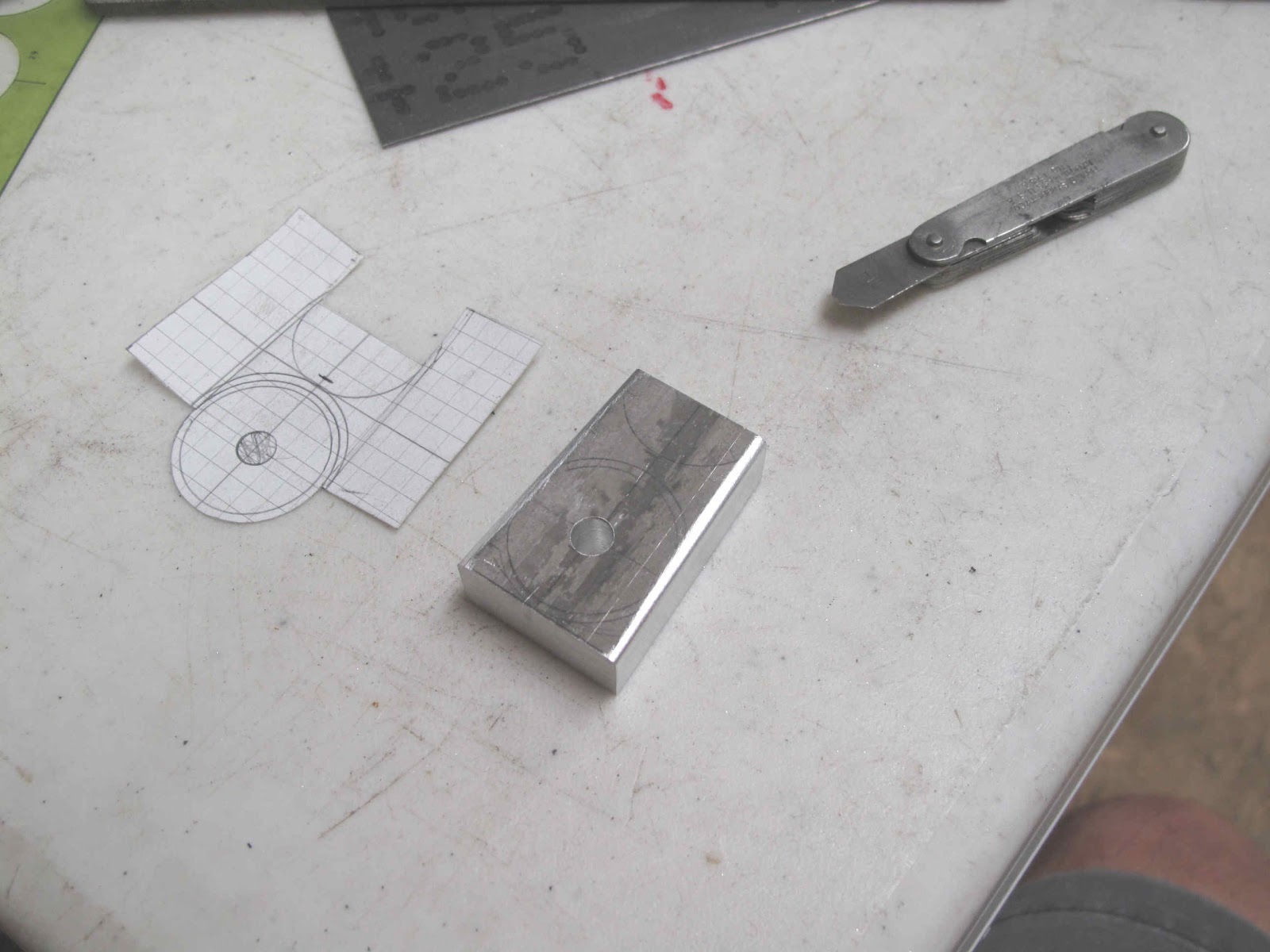
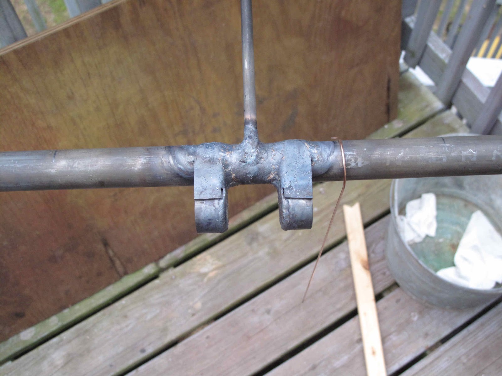
The bearing at the inboard end of each elevator also serves as the attachment bracket for the stabilizer to the fuselage. The bearing is made from a piece of 1 1/8" x .049" tubing 5/8" long. It is welded to a bracket which is folded from a piece of .050" steel (paper pattern shown). The bracket is welded to the aft side of the stabilizer rear spar. The end of the elevator spar fits into the tube and the bracket stops it from moving inboard. The hole in these brackets is for bolting the stabilizer to the tail post of the fuselage (more later).
This bearing cup is spaced out from the spar so that it is lined up with the 2 outboard bearings.
The spar on the stabilizer is made from 1" tubing and the bearing socket is made from 1-1/8" tubing so the bracket tapers from end to end. The easiest way to get this right is to make a form block to bend the bracket around. The only scraps I had that could take the pressure of bending .050" was some 1/2" thick aluminum. The 1/4" bolt hole makes a nice locator for holding the steel in position while bending it.
To get nice square sides on the bracket the sides of the block need to be ground to more than a 90 degree bend to allow for spring back. I ground this to 4 degrees past square. I should have used more like 5 or 6 degrees. Setting such small angles on the belt sander is easy by using a little trigonometry, the tangent of the angle = the rise over the run.
Aluminum heats up very quickly so it's easier to hold with some pieces of wood. I first ground the front to back taper to just touch my scribe line with the table square to the belt. When I added the spring back angle I carefully ground to just remove the scribe line.
The edges where the bend is formed were then filed to a 1/16" radius. I like to use the radius gauge to assure I get the radius I intend.
To make the steel blank I first made a template from some galvanized steel. I can screw it up several times without wasting expensive 4130 steel. The bolt hole is then drilled in the steel. The hole makes a nice a locator for scribing the cut lines. I use a felt marker before scribing like using die ink but easier. It realy helps to see the line.
The blank is then bolted to the form block and clamped in the vise for bending each side. The bend always comes out better if you hammer on a piece of hardwood rather than directly on the piece you're bending.
A nicely formed part.
To position the bearing cup and hold it in position I used a bolt and AN970-4 washer. The washer is 1-1/8" in diameter so it lines up perfectly with the outside edge of the tubing and clamps it very well. Where the tube welds to the bracket I left about 1/64" of bracket past the scribe line to make welding easy. It also leave the scribe line easy to see for aligning the tube.
I welded the outside edge and about 1/2" of the tube to the middle of the bracket. The tabs get welded to the tube when everything else is done.
With the parts welded the cut out for the stabilizer spar could be made. It made forming and welding easier to to this after welding on the tube.
A piece of 3/4" tubing, with square ends, was cut 1-9/32" long as a spacer for the brackets. The tail post on the fuselage is 1-1/4" tubing. With this assembly bolted together it was clamped to the rear spar. A straight edge was used to align the Inside Diameter (I.D.) of the beading with the O.D. of the spars
One clamp at a time was remove to allow the assembly to be tacked to the spar. The ends of the tabs were then heated and bent to fit the spar. I don't normally bend 4130 hot but the area gets reheated to weld it. These parts should have been formed and positioned before assembling the stabilizer. After welding the brackets and tabs to the spar the bearing ends of the brackets were bent slightly to maintain the gap and square up the bearings before welding the tabs to the bearing tubes.
The outboard bearings could now be welded in position. First the ends of the tubes were drilled out to fit some stainless 10-32 screws. The screw just set there to hold the tube and bearing in position while welding the tube to the bearing. I should have welded these assemblies before assembling the stab. as well. Live and learn. They're turned 90 degrees to their correct position to make it easier welding the small tube to the bearing strap ends.
A piece of 1" tubing is inserted into the bearing cup and clamped with sticks to align it with the spars. This tube holds the bearings in position while tack welding them to the stab. Once these were tacked on, it was to dark to finish welding so I'll just have to wait for another calm evening. The bearings all line up great. I really need to go fit this to the fuselage.
Wednesday, June 6, 2012
Saturday, June 2, 2012
Rudder Repair
I ordered some pieces of tubing I need to finish the stabilizer, so while I wait for them I decided to repair the rudder. The trailing edge tube has been repaired, badly, a few times and is missing a section. I bought enough tubing to build a new one but I would like to have as many original parts in the plane as I can. The first step was to layout the the rudder on the jig I made for the horizontal tail. The board needed to be a little wider so I added a piece of wood to one edge. The balance horn part of the rudder is in good shape or I would have needed to build a whole new jig board to get it all to fit. With the layout complete I formed the new trailing edge from 5/16" tubing using the same methods as the elevator Trailing Edges and Stabilizer Leading Edge.
With the new trailing edge formed I'm ready to cut off the old one. The top section, the middle section and the bottom section have all been damaged. The ends of all the ribs are still the factory welding which makes it easy to see how it was all done.
I used a 3" cut-off wheel to remove the trailing edge. I left a little of the trailing edge to clean up with better tools. A 4" grinder, mill file and rat tail file worked great to clean off all the weld and trailing edge tube.
Everywhere I opened tubing it was in great condition. To see how the bottom end of the Trailing Edge was attached to the Spar I removed the piece closing the bottom end. The trailing edge is welded to the back of the spar and passes through to the front but is not welded to the front. The tube is clean and free of rust.
The spar is clamped in place on the jig. I started fitting the Trailing Edge at the bottom so splice at the top could be made to fit better. It's clamped in place as are the ends of the tubes.
The splice at the top is made at the top of the spar so there is more to weld the ends to than just each other. I also fit a piece of 1/4" tubing inside. I'll weld it into the joint.
The 2 tubes for the top rib had a lot of rust near the rear end so I've cut them off and will splice on some new tubing. Again a piece of 1/4" tubing is sleeved inside. To keep it positioned while sliding on the new tubing a small hole was drilled and a piece of weld rod inserted as a temporary stop. I'll weld up the holes.
Everything is fitted up ready for welding.
I got it tack welded before I lost the daylight, so I'll finish welding in the morning. I like it.
With the new trailing edge formed I'm ready to cut off the old one. The top section, the middle section and the bottom section have all been damaged. The ends of all the ribs are still the factory welding which makes it easy to see how it was all done.
I used a 3" cut-off wheel to remove the trailing edge. I left a little of the trailing edge to clean up with better tools. A 4" grinder, mill file and rat tail file worked great to clean off all the weld and trailing edge tube.
Everywhere I opened tubing it was in great condition. To see how the bottom end of the Trailing Edge was attached to the Spar I removed the piece closing the bottom end. The trailing edge is welded to the back of the spar and passes through to the front but is not welded to the front. The tube is clean and free of rust.
The spar is clamped in place on the jig. I started fitting the Trailing Edge at the bottom so splice at the top could be made to fit better. It's clamped in place as are the ends of the tubes.
The splice at the top is made at the top of the spar so there is more to weld the ends to than just each other. I also fit a piece of 1/4" tubing inside. I'll weld it into the joint.
The 2 tubes for the top rib had a lot of rust near the rear end so I've cut them off and will splice on some new tubing. Again a piece of 1/4" tubing is sleeved inside. To keep it positioned while sliding on the new tubing a small hole was drilled and a piece of weld rod inserted as a temporary stop. I'll weld up the holes.
Everything is fitted up ready for welding.
I got it tack welded before I lost the daylight, so I'll finish welding in the morning. I like it.
Monday, May 28, 2012
Elevator Hinge Bearings
The elevators are attached to the stabilizer with a socket at the inboard end (my next task). in the middle and at the outboard end there is a little bearing block formed from a strip of 1/2" wide .050" steel. You can see the middle one in this picture just outboard of the control horn. The outboard hinge has a 3/4" wide strap of .050" steel which holds the elevator spar into the bearing. The middle bearing is just pulled snug by the control cables. The 2 elevators operate independently.
To form the bearing strap I started with a 6" strip of steel with bend lines marked 17/32" either side of center. As with the hinge block clips I'm forming the bends with my sheet metal pliers with a radius filed on the edges.The bends are made to form a triangle.
The formed strip is slipped over one side of the sheet metal pliers with the jaws open. The pliers are setting in the vise to provide something to pound against.
The plan is to use my 5/8" deep socket as a form tool to pound the curved bearing surface into the strip. I found that after just starting the bend I needed to clamp the sides tightly to keep the sides spaced correctly and parallel. Once it's done you have a nice bearing.
I did find I needed to twist the legs slightly to square them up to the bearing surface. I clamped each part to a piece of 1" tubing and the adjusted the legs to square.
I made this little fixture from a piece of aluminum angle. There is a 3/16" bolt which goes through the strip in front of the stabilizer rear spar. A small piece tubing gets welded to front of the spar for this bolt. The purpose of the fixture is to punch the bolt holes in the legs of the bearing strips.
The tab bent over on the fixture is a stop to locate the bearing relative to the hole so the 2 holes are on a line perpendicular to the legs.
With the holes punched the legs can be trimmed to length and the bearings are ready to weld to the stabilizer. I believe the factory probably welded the small tube and bearing together as an assembly and slipped them over the spar during assembly into the stabilizer jig. It would make welding much easier. I've got the stabilizer assembled so I'll just need to be careful welding all this in place.
To form the bearing strap I started with a 6" strip of steel with bend lines marked 17/32" either side of center. As with the hinge block clips I'm forming the bends with my sheet metal pliers with a radius filed on the edges.The bends are made to form a triangle.
The formed strip is slipped over one side of the sheet metal pliers with the jaws open. The pliers are setting in the vise to provide something to pound against.
The plan is to use my 5/8" deep socket as a form tool to pound the curved bearing surface into the strip. I found that after just starting the bend I needed to clamp the sides tightly to keep the sides spaced correctly and parallel. Once it's done you have a nice bearing.
I did find I needed to twist the legs slightly to square them up to the bearing surface. I clamped each part to a piece of 1" tubing and the adjusted the legs to square.
I made this little fixture from a piece of aluminum angle. There is a 3/16" bolt which goes through the strip in front of the stabilizer rear spar. A small piece tubing gets welded to front of the spar for this bolt. The purpose of the fixture is to punch the bolt holes in the legs of the bearing strips.
The tab bent over on the fixture is a stop to locate the bearing relative to the hole so the 2 holes are on a line perpendicular to the legs.
With the holes punched the legs can be trimmed to length and the bearings are ready to weld to the stabilizer. I believe the factory probably welded the small tube and bearing together as an assembly and slipped them over the spar during assembly into the stabilizer jig. It would make welding much easier. I've got the stabilizer assembled so I'll just need to be careful welding all this in place.
Sunday, May 27, 2012
Welding Horizontal Tail
I decided after all these years to take a weekend off and just work on airplanes, no embroidery. The weather was forecast to be hot and fairly calm so a good weekend for welding. Because I'm using 4130 steel I still needed a place where I could work without any drafts. I set up one of the 10'x10' tents I use for selling embroidery at shows as a temporary welding booth. The side flaps zip completely shut. If you open some gaps at the top of the sides you get ventilation without the breeze. The side are so light the slightest breeze will move them. Early mornings and evenings were breeze free all weekend.
A variety of saw horses, clamps and hooks made of welding rod made positioning the parts fairly easy. There is a lot written about welding fuselages to prevent warping but I found nothing specifically on welding long flat tail surfaces. Fortunately the general principals apply. The best way to weld the stabilizer seemed to be to start welding in at the center rib and work outward 1 rib at a time on each side. The other thing is to weld the rib to both side of the spar before moving to the next joint. Luckily if you forget or the spars warp a little because they will, you can fix it fairly easy by heating the tube. You do this on the high (convex) side of the tube where you want to straighten it. In my case I heated the spar from the weld out about 3"-4" beside the rib. I heated it to a dull to bright cherry red along the to 1/3 of the spar and then let it cool. As it cools it pulls the spar back to straight. It was very cool to see it happen.
At each hinge strap there is a block of wood for attaching the fabric. To hold the blocks in place there are some clips (straps) which are held secure with a screw and nut. The clips are welded to the back of the spar.
Making the Hinge Block Clips (P/N 188) was easy. They're made from 1/2" strips of .050" steel 2" long. The first step was to punch a 3/16" hole for the screw. The hole was punched in the first part and then duplicated on the other parts.
I filed a radius on the inside edges of my sheet metal pliers for bending such parts. The bend was started 1 33/64" from the weld end. The square makes a nice gauge for setting the distance and getting the strip positioned square to the edge of the pliers. By holding the strip snug against a hard surface while forming the bend you get a nice tight bend.
I used a piece of scrap to make a little fixture to hold the spacing and clamp to the to control the location, centered 9" from the tip.
Welded on ready to be formed around the wood block. At this point I've spent about 16 hours welding the elevators and stabilizer after tack welding them. I've also use 16 lengths of welding rod. They probably wouldn't hire me at WACO but it was good fun and worth every minute spent in the tent in 80-90 degree weather. I'm just delighted.
A variety of saw horses, clamps and hooks made of welding rod made positioning the parts fairly easy. There is a lot written about welding fuselages to prevent warping but I found nothing specifically on welding long flat tail surfaces. Fortunately the general principals apply. The best way to weld the stabilizer seemed to be to start welding in at the center rib and work outward 1 rib at a time on each side. The other thing is to weld the rib to both side of the spar before moving to the next joint. Luckily if you forget or the spars warp a little because they will, you can fix it fairly easy by heating the tube. You do this on the high (convex) side of the tube where you want to straighten it. In my case I heated the spar from the weld out about 3"-4" beside the rib. I heated it to a dull to bright cherry red along the to 1/3 of the spar and then let it cool. As it cools it pulls the spar back to straight. It was very cool to see it happen.
At each hinge strap there is a block of wood for attaching the fabric. To hold the blocks in place there are some clips (straps) which are held secure with a screw and nut. The clips are welded to the back of the spar.
Making the Hinge Block Clips (P/N 188) was easy. They're made from 1/2" strips of .050" steel 2" long. The first step was to punch a 3/16" hole for the screw. The hole was punched in the first part and then duplicated on the other parts.
I filed a radius on the inside edges of my sheet metal pliers for bending such parts. The bend was started 1 33/64" from the weld end. The square makes a nice gauge for setting the distance and getting the strip positioned square to the edge of the pliers. By holding the strip snug against a hard surface while forming the bend you get a nice tight bend.
I used a piece of scrap to make a little fixture to hold the spacing and clamp to the to control the location, centered 9" from the tip.
Welded on ready to be formed around the wood block. At this point I've spent about 16 hours welding the elevators and stabilizer after tack welding them. I've also use 16 lengths of welding rod. They probably wouldn't hire me at WACO but it was good fun and worth every minute spent in the tent in 80-90 degree weather. I'm just delighted.
Friday, May 25, 2012
Tack Welding Second Half of Stabilizer
You may have noticed all the holes and removable panels in my jig for the tail surfaces. The idea was to be able to stand the jig up on edge to tack the bottom tubes. The c-clamp keeps it from falling over.
The stabilizer is completely tacked, ready for welding.
There are 2 bushings in the front spar for the bolts which hold the front spar to the fuselage. These bolts don't line up with the fuselage longerons. The stabilizer front spar sets on top of the longerons and a block of wood is bolted to the stabilizer clamping it to the longerons. The center on the top of the spar was marked like when I flattened the ends. By using the same piece of paper wrapped around the spar, the center line was drawn around the spar to locate the bottom hole. I get more accurate holes by drilling from both sides than drilling all the way through. The Port-Align is clamped to some pieces of angle to hold the drill perpendicular to the spars. The holes are drilled with a center drill to control the drill better.
The bushings, ready to weld, have been left a little long so they are easier to weld. I'll grind them to length after welding.
The stabilizer is completely tacked, ready for welding.
There are 2 bushings in the front spar for the bolts which hold the front spar to the fuselage. These bolts don't line up with the fuselage longerons. The stabilizer front spar sets on top of the longerons and a block of wood is bolted to the stabilizer clamping it to the longerons. The center on the top of the spar was marked like when I flattened the ends. By using the same piece of paper wrapped around the spar, the center line was drawn around the spar to locate the bottom hole. I get more accurate holes by drilling from both sides than drilling all the way through. The Port-Align is clamped to some pieces of angle to hold the drill perpendicular to the spars. The holes are drilled with a center drill to control the drill better.
The bushings, ready to weld, have been left a little long so they are easier to weld. I'll grind them to length after welding.
Thursday, May 24, 2012
Tack Welding First Side of Stabilizer
The first side is now tack welded. I didn't weld the front spar to the ribs at this point or the spars and leading edge at the end without the ribs. I also shouldn't have trimmed leading edge tube at the far end until I flipped it in the jig. It turned out it was the right length, but again I think it was more dumb luck.
One thing I noticed when I flipped the Stabilizer in the jig was that by sliding the front spar along the blocks it put a bend in the rear spar. To make sure the rear spar was straight I clamped it first and then clamped the front spar so that the rear spar was straight.
Everything is clamped ready to fit the ribs.
When forming the bend at the front of the ribs I held a piece of 1" tubing in the formed end at the rear so I could see that the bend would be made in the plane of the rib. Otherwise the bend will wander to the left or right.
Shims under the bottom rib tubes hold them tight to the spars and leading edge. The pieces of tape are there to hold the top rib tubes in place while I carry the jig outside for welding.
I'm on a temporary hold on welding. When I was shutting down the tanks after tack welding the first half I noticed the oxygen line was loosing pressure before I bled it off. The problem was a scratch in the seat of the tank valve. I forgot to leak check the tank when we got it replaced last fall with a fresh tank. I've lost half the oxygen while I've been welding. I probably won't make that mistake again.
One thing I noticed when I flipped the Stabilizer in the jig was that by sliding the front spar along the blocks it put a bend in the rear spar. To make sure the rear spar was straight I clamped it first and then clamped the front spar so that the rear spar was straight.
Everything is clamped ready to fit the ribs.
When forming the bend at the front of the ribs I held a piece of 1" tubing in the formed end at the rear so I could see that the bend would be made in the plane of the rib. Otherwise the bend will wander to the left or right.
Shims under the bottom rib tubes hold them tight to the spars and leading edge. The pieces of tape are there to hold the top rib tubes in place while I carry the jig outside for welding.
I'm on a temporary hold on welding. When I was shutting down the tanks after tack welding the first half I noticed the oxygen line was loosing pressure before I bled it off. The problem was a scratch in the seat of the tank valve. I forgot to leak check the tank when we got it replaced last fall with a fresh tank. I've lost half the oxygen while I've been welding. I probably won't make that mistake again.
Subscribe to:
Posts (Atom)