Wednesday, May 26, 2010

Cutting Out Control Horns

To get the holes in the tabs and the edges of the 2 halves to line up I made a template from some scrap steel. The template is 1/16" larger than the hole in the form so it just touches edge of the corner radius. To locate the template I mark several spots along the edge of the radius on the inside of the part.
.
.


The edge of the template is lined up with the inside edge of the marks. This gets it well centered on the part even though you can't see the part while you're doing this.

Then using the duplicating punch (no nib) in the Whitney punch, hold it all tight and punch the first hole. Ok, if you look close you'll see 2 holes on each tab of my template. I mislocated the first ones and just had to be careful to use the correct holes.

Put a cleco (3/16") in the first hole. Make sure it's still lined up at the other end and punch the second hole. You could clamp all this but I didn't want to risk scratching the tabs. Because the template sits just in the radius it wants to stay where it belongs making this easier than it seems.


I made a second template 1/16" larger than the first to mark the cut line . The holes are duplicated on it from the first template. You could do this with just this template but it was hard to get lined up correctly. The first template locates the holes, this one locates the cut line. Cleco it in place and draw a line around it with a felt pen. The wide line was easier to follow with the nibbler than a pencil line.


The part is ready to cut the outline.
.
.
.
.


The nibbler works best if you push the metal at it with a steady force, you'll get a nice smooth line. I started on the inside and saved the big corners to make the end tabs which go between the shells. OK, I have a lot of steel but wasting those corners is just not in my nature.

.
.
.
.
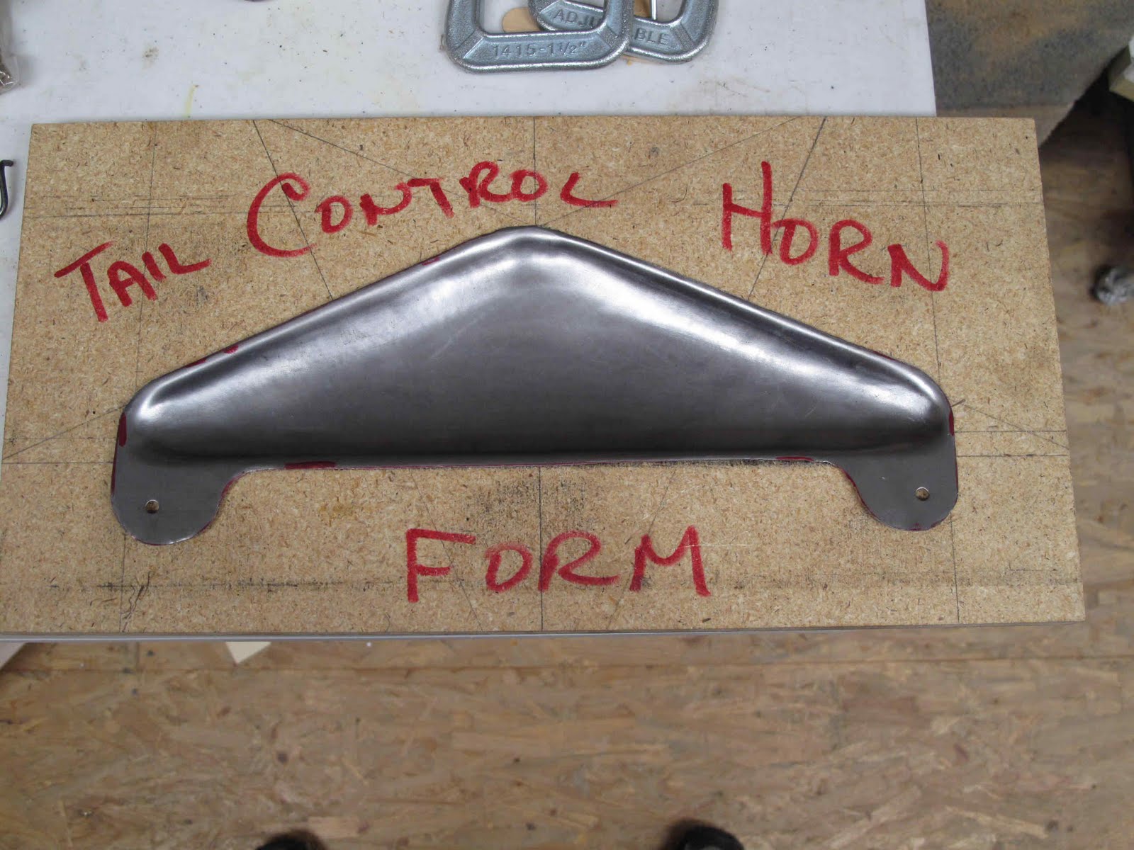


The finished part from the inside and a comparison with the original part.

The parts still need a notch at the trailing edge for the 3/4" tube and at the leading edge for the 1" spar tube.


Tuesday, May 25, 2010

Elevator Horn Forming

Having figured out how the Elevator and Rudder horns were made, the next task was to form the streamline shaped halves for welding together. We need 6 halves from 20 gauge cold rolled steel. The blanks are cut 16" x 6". I couldn't find small pieces anywhere. Dillsburg Aeroplane Works used to sell it but got rid of all theirs, probably not a fast mover. The day before our last big snow storm I drove over to Richmond and bought a 4' x 8' sheet. Do the math I have plenty left if someone needs some.

The tools are: form blocks, clamps, air hammer, rivet gun, leather shot bag, 1/2" straight rivet sets, and some hammer tools made from 1-1/4" & 2" dowel. The form block is made 8" x 16" from 5/8" particle board shelving. I made it wider than the blank to give it a little extra strength. The hole was carefully cut and sanded to have nice straight edges and a 1/16" radius for the metal to draw over. Three tools were made from dowel by cutting 6" long pieces and drilling a 1/2" hole 1-1/8" deep with a flat bottom. I thought the dowel would need to be glued to the rivet set but it was a tight fit and as it gets used it warms up and sticks in. Glue might have solved the problem of the hole deepening and the need to cut off the hole end after each part was made. For six parts I just kept cutting them shorter. The 1-1/4" dowel was oak, the 2" poplar. Oak is clearly the right wood since it did not need as much rework. The 2" tool was less than 4" long when I was done but, it never split. I had one of the 1-1/4" tools split along the hole. It was easier to just make a new tool than worry about how to prevent splitting.

The ends of the tools were rounded by hand using the belt sander and some hand sanding with a light casting shadows on the high and low spots. One of the small tools was cut to 3/4" wide to get into the corners. The 2" tool is almost flat on the bottom with about a 1/2" radius on the corner.
I found these vise-grips (made for holding bolt heads) worked perfect for getting the rivet set out of the wood. It really gets stuck tight. They grip without leaving any marks on the shank.

The rings are most of the ends cut off the tools as the rivet set smashed it's way deeper into the wood.
.
.
.
.
.

The sheet of steel is clamped between the form block and backing board leaving about 1/2" beyond the trailing edge point. I did all the hammering with the form block setting on the shot bag to reduce noise through the house and prevent damage to whatever was under the clamps. They do not touch the work bench (floor).


The first tool used is the corner tool. The corners seemed to stretch better if done first. I formed each corner to it's full depth and then used the same tool to form the radius all around the edge.


The next step was to use the 1-1/4" round tool to form the leading edge radius. This was blended into the corners to form a smooth transition. The middle part of the trailing edge was left unformed. It takes the least work.


The trailing edge was then formed with the 2" tool to give a nice streamlined shape. The rivet guns faster rate gives a much smoother finish. The trigger also has better control over speed and force.


Note the noise cancelling head set.


Once the shape looks good and is relatively smooth the part is removed from the form block for some gentle smoothing with the 2" tool in open areas and the 1-1/4" tool along the edges.

.

.


I actually improved this part a little more after taking this picture. The slight bumps at the left were easily removed.


Sunday, March 7, 2010

Wing Rib Progress

Steady progress is being made on wing ribs.

14 of 14 Full Light Ribs for lower wings
4 of 4 Heavy Compression Rigs (1 per panel)
4 of 4 Full Light Compression Ribs (1 per Panel)
2 of 2 Half Light Compression Ribs for upper wings

The rest of the light ribs (stick built) are all for the upper wings 8 full length and 14 short (at aileron cut out).

I need to order some more spruce to make the rest of the ribs which are all made from solid 1/4" spruce, root ribs, wing walk and, 2 outboard compression ribs for the lower wings.

I also need to finish the fittings, most of which are drilled and cut out but, need filing, bending and welding.

Monday, March 1, 2010

Compression Ribs

I built the second of the short compression ribs. One thing I forgot to say, it's easy to lightly unbend the stick slightly to fit the nose rib nearly perfectly which makes getting a tight glue joint easier.

I have one more of the full light compression ribs to build for the lower wings, they get sticks added to both side.

The compression rib for the lower wing at the tip is not made like the short one for the upper wings. It uses the same nose rib from 1/4" spruce but that's all. There also is no drawing for it. The factory assigned a part number and then some how used that number for a different part on a totally different plane, good job guys. The rib does not show up in the factory photo because all you can clearly see in it are upper wings. The drawings I have that the Air Corps made in late 1926 some how missed that rib also. They show all the other rib types for each wing. Both the factory drawings and the Air Corps drawings show the cap strips made from 1/4" x 3/4" spruce with a web in hidden lines about 1/4" thick, like the nose ribs and root ribs.

I found this photo (only the tip end shown here) in Foster Lane's book about Miss McKeesport. The picture, about the size of a credit card, shows an upper and lower wing for C116 in a stand after repairs when he restored it. I scanned it, descreened it and enhanced it enough to see that the rib is clearly solid spruce and from the amount of overhang of the cap strips it clearly is 1/4" thick. The trailing edge section looks shortened but I suspect they used the same rib as for the aileron cut out on the upper wings and the shortening is due to shaping to fit the tip bow. The Aileron cut out rib aft of the spar is also 1/4" spruce with 1/4" x 3/4" caps strips.

This rib isn't used on the WACO TEN (improved NINE) because the TEN has ailerons on both upper and lower wings. Why on earth they made every compression rib different is beyond me. They Clayt and Sam were not engineers so it's hard to imagine any precision knowledge of different loads at each rib. They did work at Aeromarine during the war which is where they got the airfoil. I've seen other planes designed with this airfoil and the details are identical on the full light ribs. I suspect all or much of this came from some Aeromarine report which we just have not yet discovered. Ah, the quest for knowledge!

Sunday, February 28, 2010

First Short Half Compression Rib

The outboard compression rib on the upper wings is a short (ends at the rear spar) light rib with a compression stick glued on the inboard side. There are some blocks which get added to the nose rib after the gussets are all on so it fits the jig. I temporarily modified the rib jig to clamp the upper and lower sticks tightly to the solid nose rib. Some pieces of carpenter shims and scrap sticks made this easy enough for 2 ribs.

These more than the other ribs need to stay in the jig until the glue is set. I did use a few nails to help hold the nose sticks.

I also left the sticks long at the aft end until gussets are on both sides.

The gussets on the inboard side of each rib need to be trimmed before installing to fit the compression stick. I think it will be installed on the rib as the rib is installed on the wing to get the bolts in and make it all fit correctly.

Rib Leading Edge Fixture

I want the leading edge stick to form a nice straight line when it's installed. Therefore the ends of all the ribs need to be cut to match. To do this I made a simple fixture to use on the table saw to cut the angle on the leading edge of the ribs. The cut is tipped 16.5 degrees from the spar which is both easy to locate from and relevant to getting the leading edge straight.

The references to hold the rib are the front and bottom of the spar, and the top of the rib at the nose. I've since removed the stop below the nose. The other 2 in front of the spar and at the top of the spar are just there so I don't grossly misalign the rib and ruin it.

I hold the top of the fixture with my finger tips and the bottom of the rib with my thumb while cutting and it all works very well. The next time you come back to do another stack of ribs it's easy to align the blade with the front of the fixture, just don't cut into it and slowly make it shorter.

The guide stick is glued and screwed to the bottom of the board and everything laid out from it.

Friday, February 26, 2010

Heavy Compression Ribs Finished

All the sections for the Heavy Compression Ribs are finished. They'll be assembled on the wings to assure a tight fit to the spars once the regular ribs are installed. There are only 2 aft sections because the upper wings are cut out for ailerons. On those ribs there are only short sticks added over the spar. The ends of the sticks do not follow the top of the center section but, are bent down so the end of the stick does not touch the fabric on the top of the wing.
