The second thing I wanted to do was change the depth of the channel pocket to allow more wiping of the sides of the channel to assure square flat walls. This one I only needed to take down until it worked. A little over shoot on this was not likely to be a problem but it still meant re-chucking the roller.
The 3rd variable was the angle of the lead on the the roller walls. The 45 degree walls seemed to work but I wanted to be able to make them steeper if needed.
Oh yeah, John could and would be happy to turn the roller but I tend to work on this stuff in the evenings (after 12 hours in the shop) so I really wanted to make the parts my self. John lives about 30 miles from his shop and has a young family to occupy his evenings. I also had never gotten my lathe set up after building this house so all this had to be done from flat bar stock using a band saw to cut out circles, a belt sander to smooth and shape them and a drill press for the needed screw and bearing holes. Oh yeah I really wanted it all within a few thousandth of an inch square, smooth, round and concentric. What fun is life without a wish list. I bought some 3/16" x 3" wide steel from Lowes, some 1-1/8" diameter roller bearings from Tractor Supply, and a cheap hole saw, screws and a new tap from the hardware store. There was enough scrap from cutting the form from the 4" wide 3/8" aluminum to make the center roller from it. I probably would have liked a steel roller but that meant ordering bar stock from McMaster-Carr. If aluminum didn't work that would be my back up plan, you gotta have a plan.
 The first step was to saw the 1-1/8 holes in the steel and the aluminum. There would be no way to hold the disk once it was cut out or to get it very square to the hole saw. Oh yeah did I mention I had to buy enough steel for about a dozen disks. I was just delighted it would work. The edges aren't square but we're putting a big chamfer on them anyway. I drew the circles the full 3" width of the metal and just don't worry about the little flat spots on 2 sides of the disks.
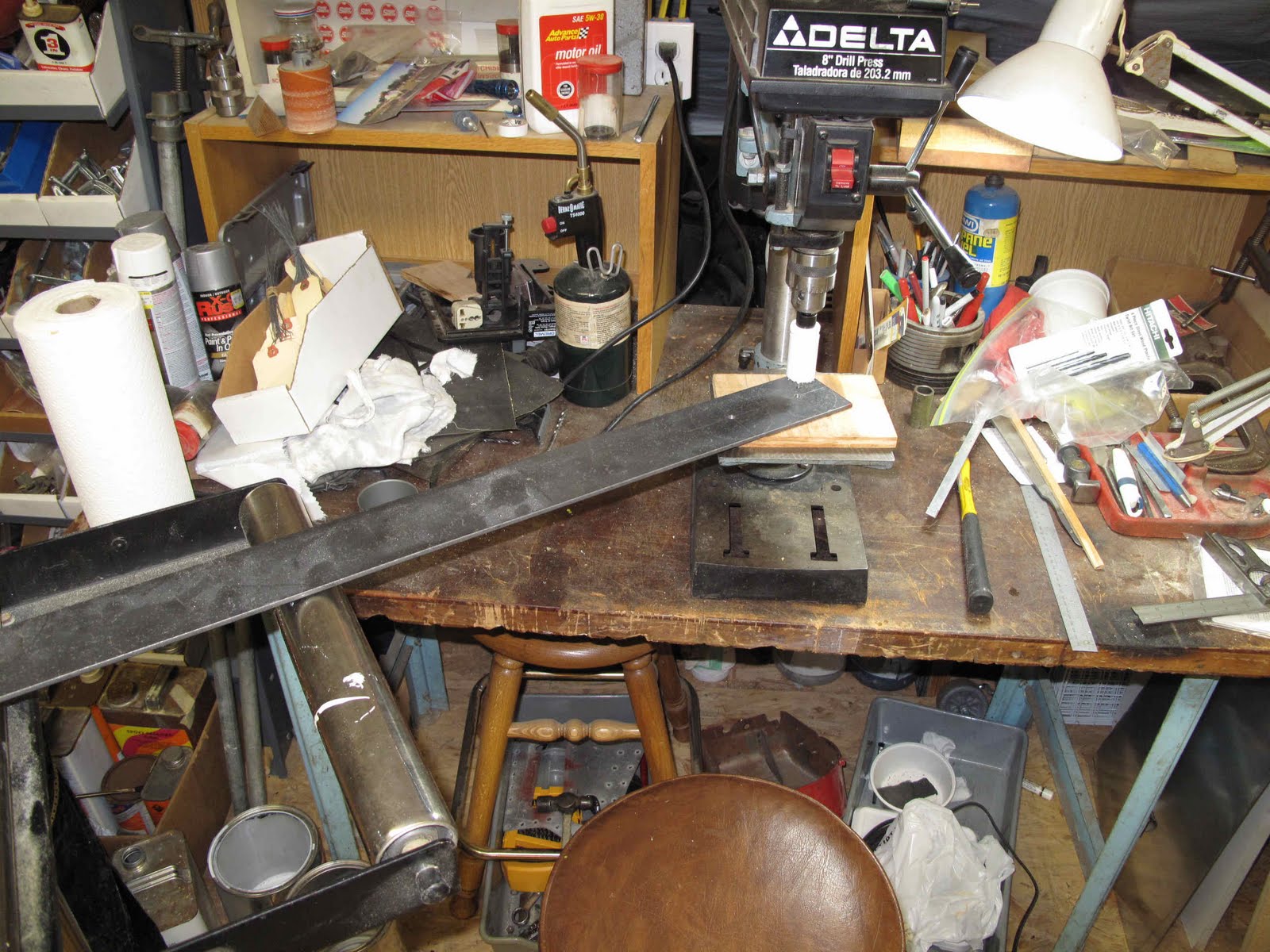 .
. .
..
.
.
.
.
.
.
 To make the outside diameter concentric with the bearing hole I bolted a stack of 3 washers (AN970-4) that just happen to be 1-1/8" in diameter to a scrap of plywood. There is a little clearance between the hole and the washers so by clamping just one end of the wood to the belt sander table you can wiggle the other end closer to the belt. By pushing the disk against the washers while rotating it you can slowly sand it round while keeping the O.D concentric with the I.D. It gets hot so I would do one a little then do the other. Eventually all the bumps are worked out and the the 2 parts are round, concentric and the same diameter. You don't move the wood in at each step until no metal is being removed as you rotate the disk.
 The same process was then used for the inner aluminum roller.
By tipping the table to 45 degrees and using the same process the edge of the outer walls we chamfered while keeping the chamfer concentric as well.
 The surface finish is rough but the shape is spot on.
 .
.
.
.
.
.
.
.
.
.
.
 A test fit and it looks like our roller. So now the ground surfaces need to be smoothed without losing our shape. Break out the 10" mill file. This works if you can turn the parts so we need a way to spin them. I had a rubber mandrel for a 1" sanding drum. To small to fit our 1-1/8" holes. I also had a rubber stopper on some 5 gallon water jugs I use in the field for measuring the permeability of soil (how fast water flows through the dirt). I had already drilled a 5/16 hole in the middle which fit the mandrel perfect and they were about 1" tall. So now I just needed to cut and sand one down to 1-1/8" just like I did the disks. Hey it worked on steel and aluminum why not rubber. We used to grind rubber parts at AC by freezing them so I knew it would work if I was careful not to overheat the rubber.

 .
.
.
.
.
.
.
.
.
.
 Voila! A mandrel to hold the parts in the drill press while lightly filing them smooth.
 I know it looks nutty but it works and they came out great. Also all of this works if you need to change angles on the chamfers or the diameter of the inner roller without losing the concentricity of the parts. It was easier to file the outer disks with the chamfer turned out.
 Now we just need to screw all this together and we'll have a roller. By using the mandrel to hold the parts concentric, and my father-in-law's machinist clamps to hold the stack tight, holes can be drilled through the stack. The holes have to be the diameter for tapping the holes. There are six holes. Three flat head screws from each side are tapped into the opposite side. Once the tap holes were drilled the parts were disassembled, marked for re-alignment and the clearance holes drilled & Countersunk.
 .
.
.
.
.
.
.
.
.
 The six hole were then tapped. One thing I would do different is to use the center roller as a guide to keep the tap square. One hole was off just a little from square making the screw a little tight. It worked but the problem could have been avoided.
 The screws were a little long so I used a washer on each one as a guide to belt sand the screws to length. At this point there are no shims to make the clearance for the .025" aluminum so the washers worked perfect. As soon as the belt kisses all three you're done.
 Shims were made from .020", .025", & .032" aluminum sheet. With a .025" shim on each side it's line to line. I started with .020" on one side and .032" on the other which give .002" clearance. I tried other combinations but that worked perfect, go figure.
 .
.
.
.
.
.
.
.
.
 The finished roller. The only other thing I did was to polish the working surfaces with crocus cloths, and then jewelers rouge on a pad with the Dremel tool while spinning the disks on the mandrel, nice finish.
On to the form block.


No comments:
Post a Comment