The turtle deck is the assembly of stringers which round the top of the fuselage behind the pilot cockpit. This picture was taken in the WACO factory 28 June 1926, within days of my plane leaving the factory. They have a lot of planes being assembled. There are some of the turtle decks hanging on the far wall.
On the plane in the bottom left, there are some little blocks of wood at the forward ends of some of the stringers. When I first saw these on my plane I thought they were a repair, but there they are, in the factory, in the exact same positions. More on these later.
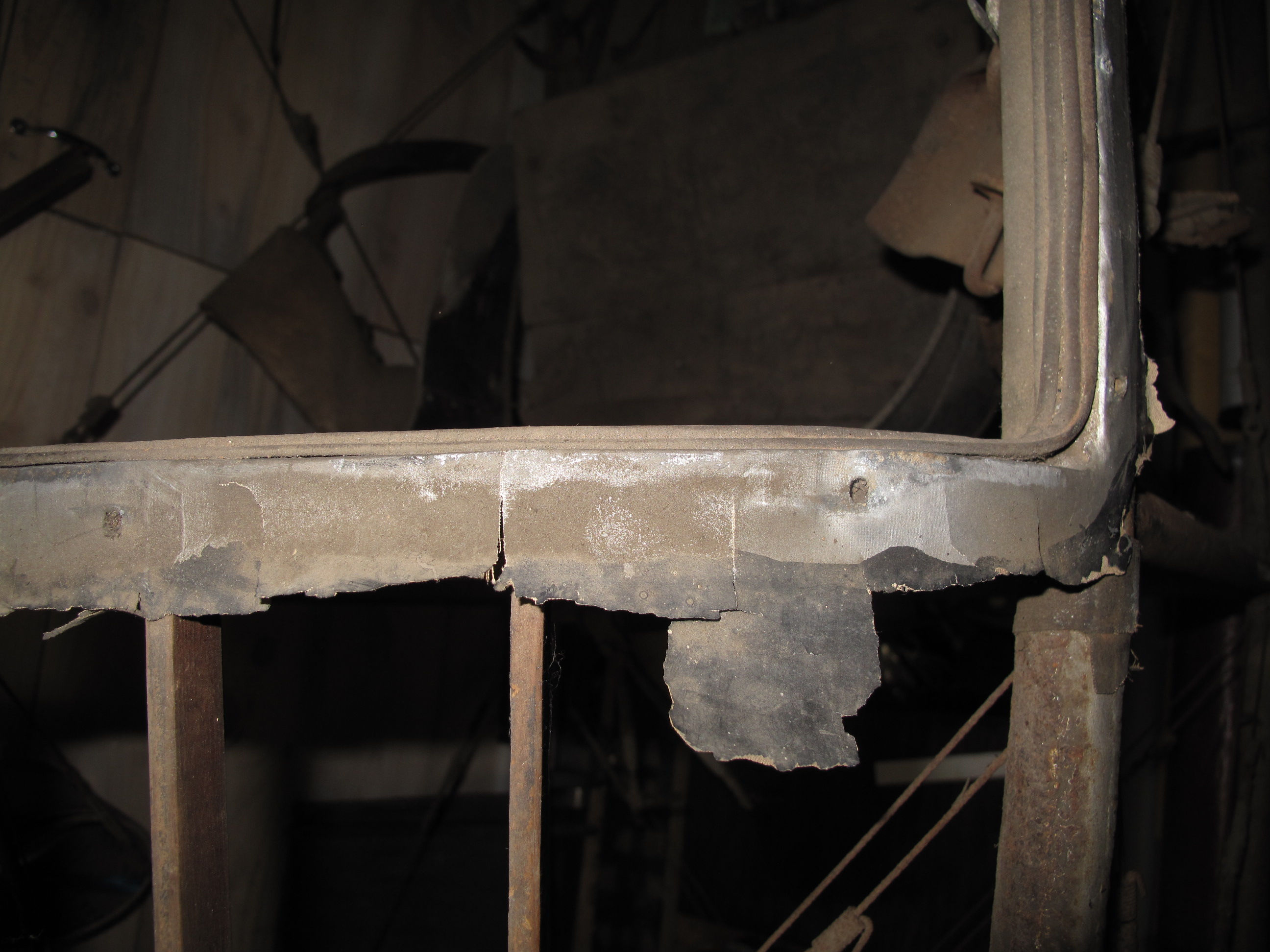
The turtle deck on my plane is damaged a little but not bad for something that's 98 years old.
It's really pretty simple. There are 11 stringers, 3 plywood formers, a spruce former at the aft end, and a piece of plywood covering the forward end. The pilot seat looks like it rubs on it, but the seat actually hits the cross tube .
The light color spot is from a mud dauber nest, hangar rash.
An interesting little item is the hole in the lower right corner, behind the pilot. I have a newspaper article from 1929 when they wired the plane with position lights powered by a dry cell battery. They flew it in the dark of night. Braver than me.
The guy on the left is Benson Spangler, 2nd owner. His son, Benson, let me handle the goggles dangling from his hand. The other fellow is "Shorty" Nelson, the 1st owner
The trim piece along the edge of the cockpit is a piece of Hide-A-Tack welting, also call Tack Hidem. Because of all the Model A Fords, it's still available. It gets tacked on through the sewn gap in the middle and covers the tacks holding the fabric covering in place.
The front plywood cover piece is flush with the top of the stringers, which all stick up 1/8" above the formers.
The coolest thing I discovered when I got the fuselage in 1996 was the factory Construction Number 264 written in pencil on the back of the plywood cover piece. The official serial number was stamped 1/8" high on the leading edge of the right hand flying wire fitting, which was welded to the lower longeron. That's about a foot in front of where my fuselage was sawn in half. It appears the factory wrote the number on the turtle deck of all the planes, where it was more easily seen by t he workers. That fancy font style was only used for the drawing numbers on the oldest drawings. Because of that hand written number I was able to get the records from the FAA and track down the son of the last owner. I also talked to the fellow who cut off the front of the fuselage with a hacksaw, in 1939. In the end I have lots of evidence that this really is fuselage number 264.
The bigger blocks of wood between the stringers were added in 1931 so they could install a WACO TEN headrest. I don't plan to reinstall it.
The slim stringer former is notched to hold the stringers, which don't continue into the full plywood cover. All the plywood is 3 ply 3/16" Mahogany. The former is nailed to the front plywood cover from the aft side.
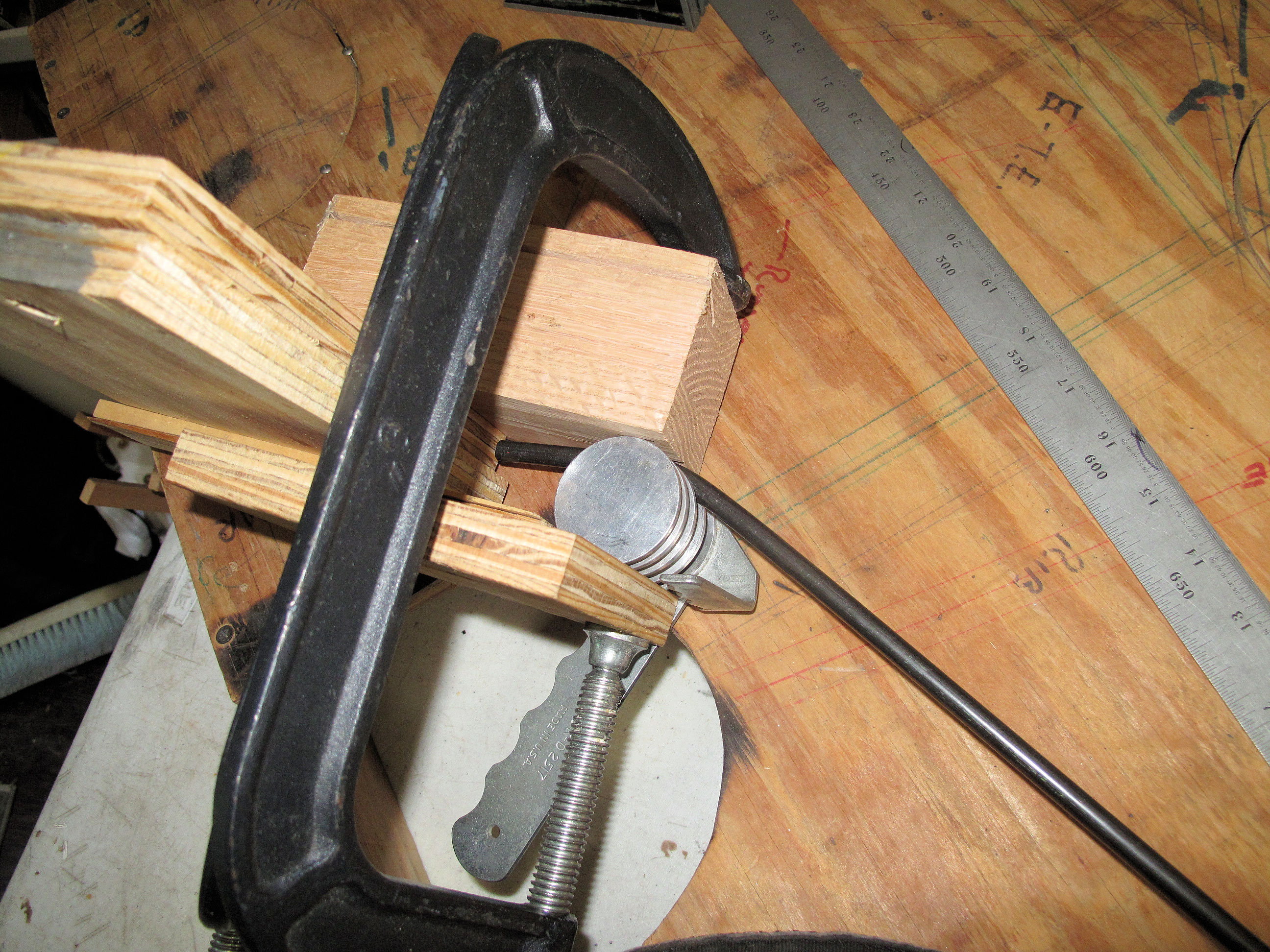
So here are those little wood blocks. They provide places to install wood screws to attach the cockpit cowling
The blocks are each nailed to the former with 2 long aircraft nails. There is no evidence of glue used anywhere on the turtle deck. The blocks are hand shaped on the top so they don't poke out under the fabric covering.
The ends of the second former originally rested on the top of the upper longerons.
The 3rd former is also plywood and rested on the longerons.
None of the formers were placed such that they were centered on the cross tubes.
You can see more clearly here that there are 3 different stringer shapes. The center one is 3/4" x 1/2" so the fabric panels on each side were tacked to this stringer. The 2 outer stringers are 3/4" x 3/8". The others are all 3/4" x 1/4". All stringers are spruce with a 3/8" radius on the upper edge.
All stringers are attached to the formers with a diagonal nail into the plywood.
The 4th (aft) former is made of 5/8" thick spruce. The 2 side stringers are tipped at 30 degrees. The rest are vertical.
This former was not attached. The others were screwed to little steel tabs. The 2nd and 3rd formers hold the stringers such that they put about a 1/2" sag in the stringers helping to hold the aft end down. I used a straight line in this area of my 1927 photo of the plane and the sag is really there.
There are 2 little blocks of 5/8" square spruce on the bottom of this former to hold it from moving sideways.
The stringers are tapered for the last 6", to a height of 5/8", flush with the former.
There are 6 tabs for mounting the plywood formers, welded to the upper longerons. They are made of .050" steel, 3/4" x 1-1/4". They have a curved bottom to fit the 1" dia. longerons and are welded only on the aft side.
They are all tipped toward each other. For the 1st former they are tipped so the holes are 29-1/2" center to center, and located 1/4" forward of the aft edge of the cross tube.
For the 2nd former the tabs are tipped so the holes are 23" center to center, and located 1/4" forward of the forward edge of the cross tube.
For the 3rd former the tabs are tipped so the holes are 17" center to center, and located 3/8" forward of the forward edge of the cross tube.
I've taken the turtle deck off the fuselage and have it downstairs in our embroidery shop. I really didn't understand how long this thing is. It's 1-1/2" short of 7 feet.
I've modeled the forward and aft formers in CAD and I'm working on the middle 2 formers. When I'm done I'll have drawings for all the parts. Then I'll start making parts.


