Showing posts with label Fittings. Show all posts

Sunday, May 8, 2022

Finally Back to Making Things - Well Almost

 The storm of January 3rd has kept me busy cutting up fallen/damaged trees for months.  I'm finally done with trees for this year.

I like to think I'm a good draftsman, but I've drawn this template on steel 3 times to get it right.

When I got it finished I decided to lay it on the drawing just as a final quality check.  I'm glad I did.  Some how I've located 2 holes incorrectly.  Pretty sad given I'm laying it out from my own drawing.

The good news is I'm having fun, even if I get to do this one more time.  Still, better than wrecking some expensive 4130 steel.

Back to the workshop.


Monday, April 20, 2020

Wires for Upper Wing Also Fit Checked

I decided I wanted to finish the drag wires for all 4 wing panels, while I remember what I'm doing.  The only way to be sure the wires will fit in the upper wings was to assemble one wing far enough to install the wires for a test fit.
 The first step was to install the fittings for the interplane struts.
 I did this a little different than on the first lower wing.  I started by pushing the end with the 3/8" bolt down, rather then the whole fitting.  It made it easier to wiggle it into position to install the bolt.  With the bolt in, the fitting was rotated to align the other bolt holes.  Again all the care to drill well aligned holes paid off, the bolts all fit perfectly.


 One of the full ribs on this wing is used as a compression strut, more on that later.  This rib needs the vertical stick notched for the drag wire clip.  I marked both sticks but only the interior sticks at the front and rear spars need the notch.  The clips are only on the wire side of the spar.  I cut the notches with a coping saw, quick and easy.
 I know this looks odd but the upper wing ribs end at the rear spar, in the area of the aileron.  The aileron hinges bolt directly to the rear spar.

It seemed to me easier to snap the rear spar into the ends of the ribs once the first full rib was started onto the spars.

You have to carefully spring the ends of the ribs open slightly to get the spar in.  I started that at the root end and worked one rib at a time to toward the wing tip.
I worried about breaking a rib but it worked out as well as I had hoped.


 With all the ribs on I started installing the wires only to discover I forgot to drill one bolt hole on the rear spar near the wing tip.
 I found it easier to install the wires with the wing upside down.

Adding the missing hole was easy enough using my Port-A-Lign to get a good square hole.

As with the lower wing all the wires fit perfect using the drawing dimensions.

I'll finish all the wires, then get back to wing assembly.

Saturday, April 4, 2020

Eyelets for Drag Wire Fittings (Wire Clips)


 The Drag and Anti-Drag wires which hold the wing rigid are made of 0.125" Piano Wire and attached to brackets called Wire Clips.  To protect the wire, a copper eyelet is formed in the wire hole of each clip.  It gives a round edge to the hole and more surface area for the wire to bear against.  On cable we use an AN-100 thimble.  I assume this eyelet was a carry over from WWI because they used AN-100 thimbles on all the external cables bracing the wings, etc.  Thimbles seem like they would work fine for these wires,  but I'm having fun making eyelets, so onward.
 I first considered 1/4" diameter, 0.035" wall thickness, soft copper coil stock, which makes a beautiful eyelet.  However the drawing calls 1/4" x 0.049" hard drawn tubing.  I ordered four 12" lengths from OnlineMetals.com
I got 4 pieces because they were only $2.67 each and it allowed me to cut off 8 ends at a time to make the 24 eyelets.

 I started by lightly  grinding the ends square while rotating them.  It makes a nice square end.  Then deburr the ends.

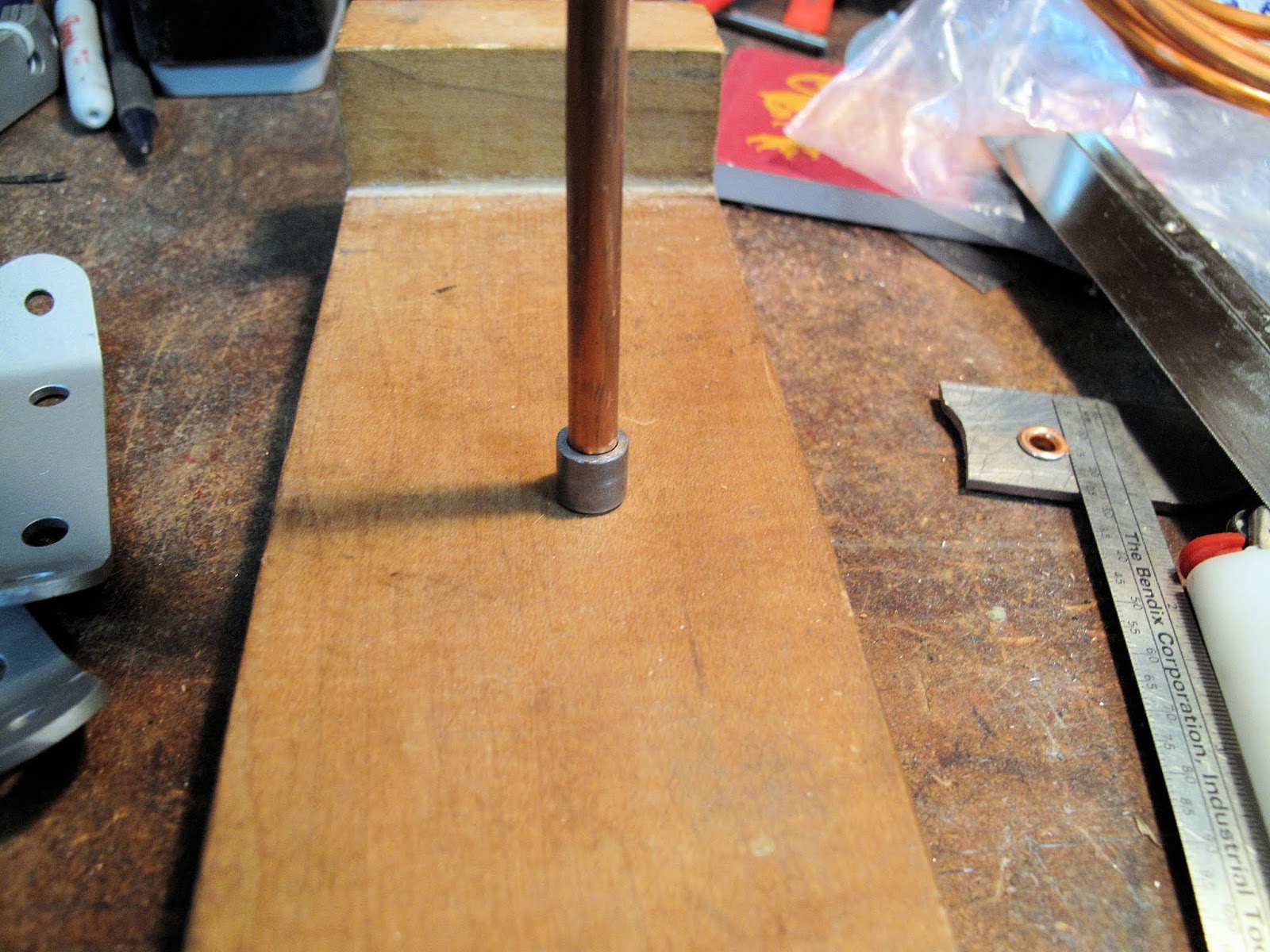
 The drawing says to make them 9/32" long so I made a gauge bushing from a piece of 4130 tubing that fit nicely over the copper tubing.  Both ends were lightly ground square, as above.
 The bushing was used to mark a ring around the ends of the pieces of tubing, 9/32" from the end, with an Exacto Saw.  It just needs to be deep enough to see while cutting off the piece of tubing and grinding the end square.


 I cut the copper pieces off with the metal cutting band saw.  Slowly rotate the tube while cutting.  I cut almost all the way through, leaving a tiny tab connecting them.  Then break the piece off.  It's better than hunting around the floor for them.
 Next I needed a way to hold the pieces while grinding the sawn edge square.  A 3/16" masonry drill bit, some Gorilla tape and a piece of 1/4" aluminum tubing worked perfect.  Obviously I could have used a piece of the copper tubing.

The idea was to leave an end sticking out about 1/4" to hold the piece of copper.


 It makes it like holding the original tube while grinding the  end square and to the marked line.  Simple.

You can also use the holder while deburring the outside edge of the piece with a mill file.


 This whole idea came from repairing some Piper Cub wing ribs using Mil Spec. 3/32" semi-hollow steel rivets.  That's what they used at the factory and it works way better than solid aluminum rivets.

I went to Hanson Rivet & Supply Co. and ordered 2 of their CA2005-29 1/4 Long Squeezer Die For 1/4 Diameter Tubular Rivet.  That's a mouthful.

I figured if you put one at each end of the tube they would form rolled over ends just like on the rivets.  It works great.  They fit my hand held rivet squeezer, which I clamped in a vice.


 You center the tube in the fitting and squeeze to form a beautiful eyelet.  Oh yeah, squeeze hard.  The factory probably did this with an arbor press or some such.

 They look like the original.  Theirs may have rolled the edge a little more, but they should protect the wire and stay put.  There is no motion to make them ever move, if they could.


 More parts done.  I did find the tubing O.D. slightly (0.002") over 1/4" so they won't fit in a 1/4" hole.  I used a 17/64" drill but a letter B size leaves a little clearance for paint,etc. and works fine.

Now I need to straighten a coil of 1/8" piano wire to make the drag wires.

Wednesday, April 1, 2020

Strut Fittings and Compression Ribs


 The fittings where the wing interplane struts and landing wires attach fit so tightly it took a little persuasion with a rubber mallet to get them on.

All the bolts fit perfectly without any redrilling of the holes.

The hole with no bolt is for a screw to hold the heavy compression rib in place.


 The heavy compression rib needs to be trimmed to fit over the strut fittings.

I used a piece of the same 0.095" steel for the fittings, to mark a cut line on the rib.

 I was going to saw the notch but realized I could carefully do most of the notch on the belt sander, wit the table squared to the belt.

I cleaned up the corner with a mill file.


 The light compression rib for the first wing bay needs a notch in the middle, fore and aft, for the drag wire clips which bolt to the spars.  There are sticks of spruce which attach to each side of the rib.  The sticks take the compression loads and they'll get cut to a snug fit, so the notch was just cut with a coping saw.