Showing posts with label Ailerons. Show all posts

Thursday, May 19, 2022

Templates For the Aileron Control Horn and Ribs


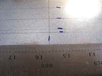
I decided to be more careful this time.  I've been using small blue tick marks to help me find my pencil marks on the galvanized steel, which I like for templates.  Depending on the light the pencil mark can be hard to see.  I confused myself on the last try by where I had made the blue marks.

I still think it makes drawing the actual lines much easier.

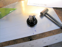
I used the optical center punch to mark all my holes and compass centers.

For holes I draw a small circle around the punch mark.  

For compass centers I put 4 tick marks, kind of like center lines.

I have this cheap plastic compass I like for most big curves. The pattern of holes and markings are set up based on the circle diameter, in 0.025" increments, so I rarely use my conventional compass.  It really works very well with my 0.5 mm lead pencil.


I drew the outline and 3 bolt holes first then added all the rivet holes.

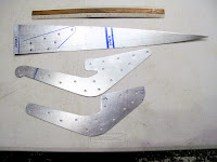
After cutting and filing the outline I punched all the holes.

There are 3 pieces which all rivet together so the holes were transferred from the horn template to the other 2 templates.  The horn gets riveted between the 1/4" spruce rib on one side and a piece of 3/4" spruce, stiffener on the other side.  The rivets are Copper Rivets used for saddle and harness making.

The rib template can be used for the full length root rib as well as the 2 piece rib at the control horn.  I'm also using it to make a small rib jig for all the aileron Light Ribs, stick and gussets.

The control horn template can also be used to make the doubler which gets welded on to the forward end of the control horn.

Making Progress!


Sunday, May 8, 2022

Finally Back to Making Things - Well Almost

 The storm of January 3rd has kept me busy cutting up fallen/damaged trees for months.  I'm finally done with trees for this year.

I like to think I'm a good draftsman, but I've drawn this template on steel 3 times to get it right.

When I got it finished I decided to lay it on the drawing just as a final quality check.  I'm glad I did.  Some how I've located 2 holes incorrectly.  Pretty sad given I'm laying it out from my own drawing.

The good news is I'm having fun, even if I get to do this one more time.  Still, better than wrecking some expensive 4130 steel.

Back to the workshop.


Thursday, January 20, 2022

Aileron CAD Drawings Finished

 Before building the ailerons, and the last 2 wings, I decided to finish modeling the ailerons in CAD.  I felt it was the only way to reconcile inconsistencies in the drawings.  I now have about 20 drawings to use building the ailerons.  I believe a good CAD model, and working drawings, help assure I only make things once.


This is the assembly drawing for the aileron.  My redraw is very close to the factory drawing.  There were no factory drawings of the detailed parts, etc.

The big change from the factory drawing is the location of the hinges.  The inboard hinge is in the factory location, but the spacing between the other hinges each change 1/16".  I think the hinge spacing on the factory aileron drawing makes more sense than the factory wing spar drawing, but I've already made my wing spars so I moved the hinges to agree with the wing spar drawing.

The shape of the aileron control horn changed slightly from the factory drawing to agree with the plane in the WACO Museum.  There were some other little issues with how the ailerons were actually assembled. The factory drawing didn't show the gussets on the ribs, or things like where blocks were needed to attach the ribs, etc.

 I now have a plan that I think will work so I'm excited to get to back to making parts.

Friday, December 10, 2021

Aileron Spars Ready to Drill

 The layout work is done on the 2 new rear wing spars.


The ailerons have 2 spars, like the wings.  The WACO NINE has ailerons on the upper wing panels only. They must Not have worked well on the 1925 version, because in 1926, with the Improved NINE, they made them longer with an Elephant Ear balance tab.  The longer ailerons would have had more power and the balance tabs would lightened the stick forces.

On the 1927 Model TEN they got rid of the Elephant Ears ears and added ailerons on the lower wings.

On the NINE the ailerons are operated by cable routed through the lower wings to pulleys hidden in the structure below the aileron control horn. You can see one in front of the aft strut and one behind it.

On the TEN they used push rods to operate the lower ailerons with the upper ailerons slaved to them by a strut between the Ailerons.

The aileron starts about 1/3 of the way along the spar and extends about 18" beyond the tip.
Each aileron is hinged with 4 hinges using an Eye  Bolt and Fork Bolt arrangement.  The fork bolt part bolts through the aft wing spar.  The eye bolt part bolts through the forward aileron spar.  I have 4 drawings showing the location of the aileron hinges, the wing assembly drawing, the aft spar drawing, the aileron drawing, and an older aileron drawing from 1926.  They all have slightly different dimensions.  There are more of these anomalies.  The aileron drawing shows the length of the forward spar is 120" but the Bill of Materials on the same drawing shows 120 1/4".

To resolve these things I've modeled the aileron in TurboCAD.  I'm using the dimensions from the drawings which work in the model.

I have all the ribs and hole locations drawn out on both sides of each spar.  I also write on the spars the size of any drilled holes.

I'll match drill the hinge bolt holes in each aileron spar by using it's wing spar as the master for the holes in the aileron spar.  Even if I measure slightly wrong the hinges won't bind.
The tip of the forward spar has a tapered tip with a gentle Ogee type curve connection the taper to the main straight section.  To layout the curves in this 8" section I clamped 2 blocks to the spar.

The one on the left is clamped flush with the straight edge, with the corner at the start of the curve.  The other block is clamped so it's edge follows the taper, with its corner at the start of the curve. 

I clamped my Starrett meter scale to the edges of these 2 blocks and drew the curve between them.  The clamps should be at the end of each block so the curve is tangent to the 2 blocks.  It was easier to do than explain.


The drawing doesn't show the taper on the aft spar so I made it such that where each rib crosses the 2 spars are the same height.  At the inboard rib the spars are 1 13/32" tall and at the outboard rib they are 1" tall.

I'm ready to start drilling, routing, etc.  We're making parts again!