Wednesday, September 19, 2012

OX-5 Blog

I expect there will be a few people interested in rebuilding an OX-5 but not my WACO project so I've created  another blog just for it and will post all my progress on the motor there.  As significant projects are accomplished I will post links to them here.

Wednesday, September 12, 2012

I now have an OX-5 Motor

While at the Antique fly-in at Blakesburg John Swander stopped by my booth to check on the progress of this project.  He had acquired 2 OX-5 motors some parts and a radiator.  After a little discussion I purchased them for $2800.  The motor you can see in the door is the most complete and hopefully restoreable. The other motor is on the other side of the van.  The motor mount is believed to be for a Travel-Air as well as the radiator.
 The valves on the best motor are Miller valves which use a grease fitting instead of oil holes in the castings.  The cylinders are also from a dual ignition OXX-6 motor.  The second plug hole is plugged with what appear to be factory made slotted brass plugs.

Both motors were made by Willis-Morrow Company of Elmira, New York.  The better motor has Manufacturer's Number M3607 but is missing the Army acceptance tag.  The other motor is number M2753 and was accepted 15 May 1918.  Since they built 12,600 engines, M3607 was probably made about a month later.


The extra parts include a header tank for the radiator and various water and intake pipes.
The prop hub on the left is not for an OX-5 but looks like it may be for a Hisso.

Some Berling Magneto cores and parts.

3 Zenith Carburetors.

Water pumps.
Standard OX-5 valve mechanisms from the second engine.
Intake manifolds.

Overall this is very cool.  The next step will be to start soaking all bolts, pistons, etc. with Corrosion X.  The plan is to clean up, repair and organize each item as it's removed.  The bigger problem is how to get the motors to the attic.  I probably will have to break it down to cylinders and case in order to store it while I'm working on each piece.

Monday, July 23, 2012

Stabilizer Incidence Angle

The stabilizer front spar lays directly on top of the fuselage upper longerons.  It is clamped there by a block of wood which sets under the longerons and is bolted to the front spar.  The brace wires are adjusted to keep it square to the fuselage center line. There is no elevator trim.  The angle of incidence of the stabilizer is not adjustable because the front spar of the fin bolts to brackets on top of the front spar of the stabilizer.  Probably not the cleverest arrangement, but it is simple.  Also the upper wing fore and aft position is adjustable with the rigging to balance the plane.

The factory fuselage drawing shows the upper longerons flat the full length of the fuselage.  On my fuselage the upper longerons are bent down 5/8" from the last fuselage bay (forward of the stabilizer front spar) to the tail post, as shown here.  The older drawing of the tail (7012) shows the same angle.  This bend lifts the stabilize angle about 3 degrees.  When Frank Pavliga test flew his NINE with the longerons straight he found a very tail heavy plane.  There are no other flying NINEs to compare handling. It looks like 5/8" is about what is needed to correct the tail heaviness.  If I ever find the lift, drag and pitching moment curves for the Aeromarine 2A airfoil I can do the math to figure this out more accurately.  The airfoil was tested at MIT in Dec. 1922 and the curves were apparently published in the 1925 edition of Handbook of Instructions for Airplane Designers.  Google claims to have the 1925 edition but its not.  I'm sure MIT has the original data and the Air Force museum should have the handbook since it was done at McCook Field.

Since I have a fuselage, this angle would have continued to exist on mine without a problem.  Unfortunately I don't have the fin so all this has been needed to figure out the correct layout of the fin to fit with the fuselage, rudder and stabilizer.

At this point I'm ready to get back to making the jig and fin.  I'm looking forward to fitting all this to the fuselage.

Saturday, June 16, 2012

Stabilizer Brace Wire Bushings

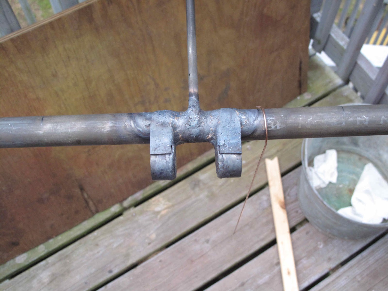
 The brace wires for the stabilizer attach to fittings which are bolted to the stabilizer with 1/4" bolts.  The bolts go through bushings, short pieces of 3/8" tubing, which are welded to the front and rear spars next to the last full rib at the tip.  I needed some way to hold these in position while I welded them.  It probably isn't critical but I wanted them nicely square to the spars and lined up with each other.  I found a piece of steel channel I salvaged from an old fold up table a few years ago.  You know, one of those things you save because some day you'll have a use for it.  Glory be, I have a use for it!  How cool is that?
I cut 2 lengths long enough to hold the bushings next to the front of each spar.  Next I punched 1/4" holes in one piece and duplicate punched them in the second piece.  That way the bushings would be parallel.
 By grinding nice square ends on the bushings with the belt sander it all clamps together tight and square.  I used Stainless Steel bolts and nuts to hold the bushings tight to the channels.  Stainless doesn't get welded into the bushing so easy if I get it a little to hot.  The little piece of welding rod was used as a spring to center the bottom end.  The whole assembly just hangs from the top bushing.  I tacked each bushing to the spar and the ribs before removing the jig.
Originally it appears the bushings were either a couple inches inboard or not welded to the rib.  The rib on the stabilizer, but not the elevator, was moved outboard about 2 inches.  I think the bushing was originally just welded to the spar and the spar probably cracked so they moved the rib out to help support the bushing better.

I still have two tabs to add for mounting the Fin front spar but I don't want to weld them until I fit everything to the fuselage, so I'm sure the holes all line up.

Thursday, June 7, 2012

Elevator Hinge Straps

 With the hinges welded on the last thing needed to make them work is the strap for the outboard hinge.  The strap is made of .050" steel 3/4" wide.
 The strap holds the elevator spar in the hinge block.  It gets bolted to the stabilizer with a 3/16" bolt.  The center hinge does not get a strap.  The inboard hinge socket we've discussed already.


 I made a pattern from card stock to work out the length of the strap and the made it 1/8" longer.  It's easy to trim off the extra once the straps are done.  I used a piece of 1" tubing clamped in place to locate and start the "U" bend in the strap.  The strap was bolted to the block and the center of the elevator spar marked as a reference for the start of the bend.  To assure the ends of the "U" line up I squared the strap to the spar.


 To hold it in place and keep the strap flat to the start of the bend I clamped it to the hinge block.  I then bent it around the tube until it hit the clamp.  You can see here that it springs back so that it is not close to the tube.  To get the correct 1/2" radius for the bend  I then clamped the strap to an 11/16" deep socket (about 7/8" O.D.).  To finish the bend it's just a matter of making sure the bend starts at the line and the legs end up parallel.


 With the strap in position so there is about 1/64" - 1/32" play in the tube The bottom hole center was marked with a 3/16" duplicating punch.  A little care is needed to make sure the drill locates the punch mark.

I need to trim off the 1/8" excess on the second end.  They came out great.  I can swap them to either elevator and they fit the same.  Very nice.  Now I need to add the bushings for the stabilizer brace wires and the tab for bolting the front of the fin to the front spar of the stab.

Wednesday, June 6, 2012

Stabilizer Attachment Hinges

 The bearing at the inboard end of each elevator also serves as the attachment bracket for the stabilizer to the fuselage.  The bearing is made from a piece of 1 1/8" x .049" tubing 5/8" long.  It is welded to a bracket which is folded from a piece of .050" steel (paper pattern shown).  The bracket is welded to the aft side of the stabilizer rear spar.  The end of the elevator spar fits into the tube and the bracket stops it from moving inboard. The hole in these brackets is for bolting the stabilizer to the tail post of the fuselage (more later).


 This bearing cup is spaced out from the spar so that it is lined up with the 2 outboard bearings.
 The spar on the stabilizer is  made from 1" tubing and the bearing socket is made from 1-1/8" tubing so the bracket tapers from end to end.  The easiest way to get this right is to make a form block to bend the bracket around.  The only scraps I had that could take the pressure of bending .050" was some 1/2" thick aluminum.  The 1/4" bolt hole makes a nice locator for holding the steel in position while bending it.

 To get nice square sides on the bracket the sides of the block need to be ground to more than a 90 degree bend to allow for spring back.  I ground this to 4 degrees past square.  I should have used more like 5 or 6 degrees.  Setting such small angles on the belt sander is easy by using a little trigonometry, the tangent of the angle = the rise over the run.

 Aluminum heats up very quickly so it's easier to hold with some pieces of wood.  I first ground the front to back taper to just touch my scribe line with the table square to the belt.  When I added the spring back angle I carefully ground to just remove the scribe line.
The edges where the bend is formed were then filed to a 1/16" radius.  I like to use the radius gauge to assure I get the radius I intend.
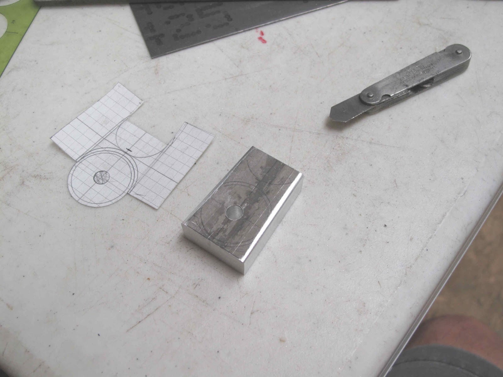
 To make the steel blank I first made a template from some galvanized steel.  I can screw it up several times without wasting expensive 4130 steel.  The bolt hole is then drilled in the steel.  The hole makes a nice a locator for scribing the cut lines.  I use a felt marker before scribing like using die ink but easier.  It realy helps to see the line.
 The blank is then bolted to the form block and clamped in the vise for bending each side.  The bend always comes out better if you hammer on a piece of hardwood rather than directly on the piece you're bending.


 A nicely formed part.

 To position the bearing cup and hold it in position I used a bolt and AN970-4 washer.  The washer is 1-1/8" in diameter so it lines up perfectly with the outside edge of the tubing and clamps it very well.  Where the tube welds to the bracket I left about 1/64" of bracket past the scribe line to make welding easy.  It also leave the scribe line easy to see for aligning the tube.
 I welded the outside edge and about 1/2" of the tube to the middle of the bracket.  The tabs get welded to the tube when everything else is done.

 With the parts welded the cut out for the stabilizer spar could be made.  It made forming and welding easier to to this after welding on the tube.
 A piece of 3/4" tubing, with square ends, was cut 1-9/32" long as a spacer for the brackets.  The tail post on the fuselage is 1-1/4" tubing.  With this assembly bolted together it was clamped to the rear spar.  A straight edge was used to align the Inside Diameter (I.D.) of the beading with the O.D. of the spars

 One clamp at a time was remove to allow the assembly to be tacked to the spar.  The ends of the tabs were then heated and bent to fit the spar.  I don't normally bend 4130 hot but the area gets reheated to weld it.  These parts should have been formed and positioned before assembling the stabilizer.  After welding the brackets and tabs to the spar the bearing ends of the brackets were bent slightly to maintain the gap and square up the bearings before welding the tabs to the bearing tubes.


 The outboard bearings could now be welded in position.  First the ends of the tubes were drilled out to fit some stainless 10-32 screws.  The screw just set there to hold the tube and bearing in position while welding the tube to the bearing.  I should have welded these assemblies before assembling the stab. as well.  Live and learn.  They're turned 90 degrees to their correct position to make it easier welding the small tube to the bearing strap ends.

A piece of 1" tubing is inserted into the bearing cup and clamped with sticks to align it with the spars.  This tube holds the bearings in position while tack welding them to the stab.  Once these were tacked on, it was to dark to finish welding so I'll just have to wait for another calm evening.  The bearings all line up great.  I really need to go fit this to the fuselage.