Tuesday, February 5, 2013

Aileron Pulley Bracket P/Ns 7033 - 7035


The ailerons on the NINE are cable operated.  This bracket holds the bracket with the aileron pulleys in the lower wing.  The pulley holder pivots on this bracket.  The cables run along the front side of the rear spar from the control stick to the pulleys and from there up to the aileron.  The bracket mounts on the front face of the spar.  The pulleys are mounted above this and parallel to the spar.
The plate # 7035 goes on the aft side of the spar because the lower bolt is actually below the spar.  The factory glued on a little block of wood but the load is carried through this plate.  Because of the odd shape and lack of a flat layout on the drawing I suspect this is another part they bought as war surplus and modified to fit by grinding off one side.  You can see the 2 bolt holes in the rear spar just to the left (inboard) of the strut fitting.

Like all the steel parts I make, I start with a galvanized template.  The material is cheap and if you mess up just bin it and make another one.  To make the actual parts I start by using the template to center punch and drill the holes in the sheet of steel, then scribe the cut lines when I'm sure the holes match the template.  If the finished holes don't match the template I can often use the steel for some smaller part if the lines haven't been scribed or cut. This method is of locating the holes is so accurate I can usually stack up a half dozen or more parts and put bolts through all the holes. The parts are cut out on the band saw and the edges ground to the line with the belt sander and drum sanders.  I always round corners and deburr every edge.  Sharp corners add weight, sharp edges don't hold paint and they draw blood.

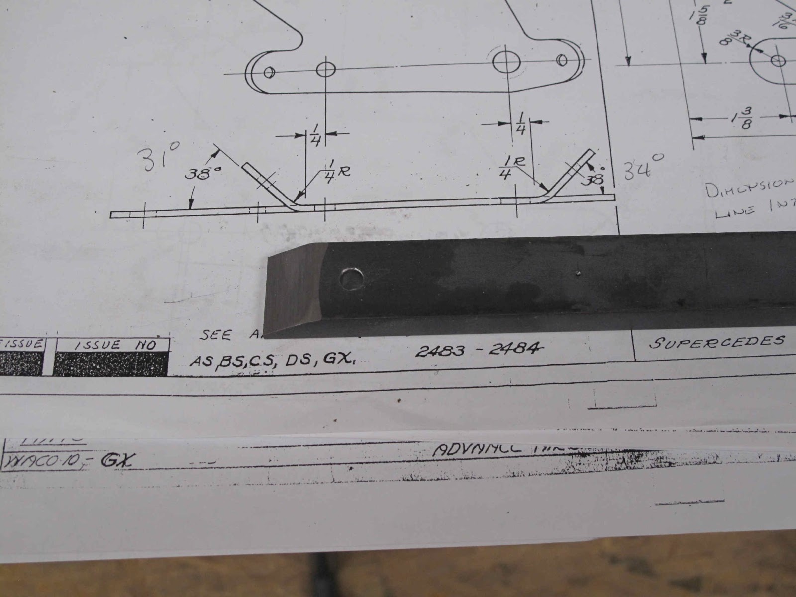
I need a form block to bend the part into a U-shape.  I'm cutting it from 1/2" thick bar stock with  a 5 degree angle to allow for spring back.  For steel this thick (.090") the block needs to be 11/16" wide to get a part with 3/4" between the legs.  The block is 4" long so cutting oil is important to protect the blade from overheating.  It also cuts faster with the oil.  I had just brazed up a new blade so the cuts were done before the Patsy Cline album album on my i-pod.  Noise cancelling earphones are a must.

With the sides cut to a fairly straight line at 5 degrees, the next step is to grind the sides smooth with the belt sander.  The part quickly gets too hot to hold so I cool it regularly by setting it on the end of my vacuum cleaner hose.  The fast moving air cools it nicely.  If you cup your hand over it to form a tunnel it cools even faster.


After grinding it smooth, if you very lightly grind perpendicular to the grinding you leave a very smooth finish.
Next the first hole is located and drilled.  In thick metal I start the hole with a center drill and finish drilling through with a regular twist drill.  The hole location is much easier to control with the center drill.  The other trick is to mark the hole location with a prick punch and then improve it with a center center punch so the drill centers in it better.
The second hole is duplicate punched using the part template to assure the holes line up with the parts when clamping everything with bolts.


The holes are drilled and the sides ground.  The drawing doesn't specify a bend radius so I used a 1/16" radius on the 2 corners.  I ground and filed the corners until they nicely fit my 1/6" radius gauge.
I made the backing block slightly off center so I could hammer close to the bend because of the .090"steel I'm bending.


I made the backing block slightly off center so I could hammer close to the bend because of the .090"steel I'm bending.


It all seemed like a good idea but I couldn't keep it in the vise when I pounded on the part to bend it.  It worked fine when I clamped it in the side of the vice, but there was no way to clamp it and bend the second side.


Back to the drawing board.  I made a longer backing block from 2 pieces of 3/16" steel left over from making the form tool for the false nose ribs.  I probably could have used one piece of steel but you have to pound so hard on such a wide bend that I felt better with 2 pieces.  I didn't want it to bend instead of the part.  The part and blocks are assembled the same as the first one.


It all clamps in the vice much better and it was easier to hammer on the top of the vice.  There is a work piece protector on the jaw of the vice to keep the bracket from getting scratched.

The part is now re-clamped in the blocks to form the second bend.  Which now can be easily done on the top of the vice just like the first bend.

It came out great.  Because there is a right and a left part you just have to pay attention to reverse the blank before making the first bend.

With the part bent the hole in the second leg can be drilled.  Because the legs are close enough together I started the hole with a center drill.  It doesn't accidentally enlarge the first hole.  The center drill is too short to make it all the way through so I finished it with a regular twist drill.

The parts are ready to paint.  I probably should make the pulley holder while my brain is on the subject.

Sunday, February 3, 2013

Bending Tabs on More Brace Wire Fittings

The rest of the drag wire fittings and the brace wire fittings for the stabilizer are now all bent.  The drag wire fittings are the stacks on the left. At each end of the spars there is a fitting with a bent tab at one end. The strut fittings and the ones to the inboard of them have tabs bent on each end.  There are a total of 6 wires, 3 drag and 3 anti-drag.  Steel form blocks were made, like the one for the strut fittings, for each of the different bends and the and the tabs hammered over them with an oak block.

The small fittings are for the 8 brace wires on the stabilizer.  I have the old ones still on the wires for the underside of the stabilizer but I may not use them if they are too rusty. The 2 on the left are bent 70 degrees and the other 4 are bent 20 degrees.  The shallow ones are at the ends of the wires at the stabilizer.  The 70 degree bends are for the ends at the top aft of the fin.  The fitting at the front of the fin fits over the pin and I still need to make it.  There is no drawing I can find for it.  The fittings at the bottom of the fuselage are welded to the structure unlike these which bolt on at the big end.

After I get the strut fittings welded I need to paint all of these and put copper eyelets on the ones where the cable loops through the holes.  The ones where a turnbuckle attaches don't get an eyelet.

Friday, February 1, 2013

Ready to Weld Wing Fittings

Now that all the holes are in the fittings and the drag wire tabs have been bent, the strut attachment clips need to be welded to the fittings.  The clips are 3/16" thick steel vs the .095" steel fittings.  Spacing the fittings is easy with some pieces of 5/16" x .028" tubing, with the length cut to the width of the spar.

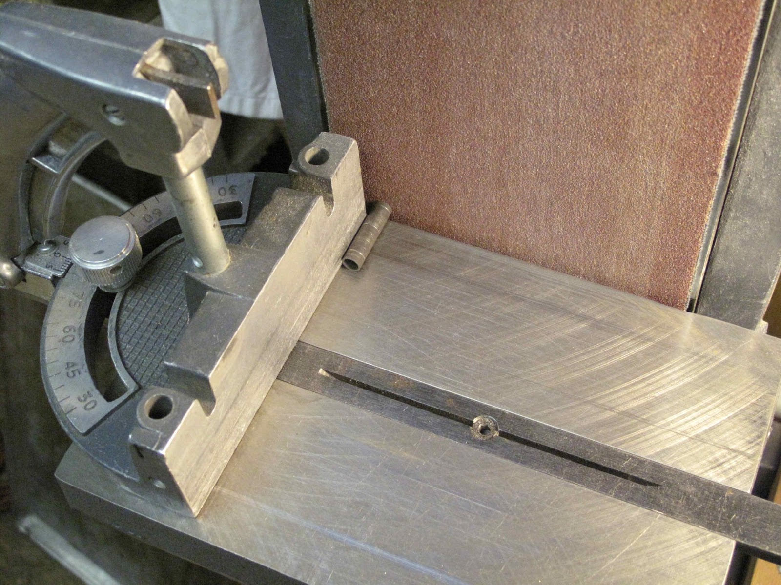
The ends of each spacer are ground square on the belt sander by holding the tube against the miter with a finger while sliding the miter across the belt.  By rolling the tube as you slide the miter and giving the tube a slight pressure against the belt you get a very square end as well as good control to create spacers all within .001" - .002" in length.  Whenever I cut off a piece of tubing I square the end of the remaining tubing right then because it's easier to do it with a longer piece than to do both ends of the short spacer.  With square ends on the spacers and a snug fit of the screws in the fitting holes, the fittings line up very well.  Check them with a square just to make sure.  You can adjust them slightly as you tighten the nuts on the screws.

With the fittings aligned, the the next problem was how to align the clip.  On the NINE it's perpendicular to the 2 lower bolts along the center line of the spar.  It also has to be a certain distance up to clear the spar and correctly positioned between the bolts.

To do all this I made some pieces of steel which locate off the 2 lower bolt bushings and then have a slot to hold the clip in the correct position. The locator piece is more or less centered between the fittings holding the clip ready to weld.

The parts are fairly simple. The bolt holes were punched from the fitting template and then drilled to fit the spacers using a center drill.  The slot was bandsawed and then filed to a snug fit on the clip.

The locator for the rear spar fittings needed a relief cut to clear the spacer part way up the arm.  I could have used less screws but it seems better to hold the fitting as securely as possible while welding.

There are 4 rear spar fittings and 4 front spar fittings so I made 2 each of the locators and spacers.  Clearly I could have done all this with 1 set of each.  Now I need the wind to die down so I can weld these.  It would be nice to have a shop where I could weld inside.

Sunday, January 20, 2013

Bending Wing Fitting Tabs

The wings are braced internally from forward and aft loads with wires called drag and anti-drag wires.  These are attached to the spars at the compression ribs with fittings bolted to the spars.  The compression ribs hold the spars apart.  Where the wires attach to the fittings, the fitting is bent at an angle to point in the direction of the wire.  This also provides clearance for the wire to be attached to the fitting.  The fittings here are installed at the compression rib where the wing struts attach.  There is a fitting on each side of the spar.  The vertical fitting welded across them is for attaching the struts.  The long diagonal  part sticking up to the right is for the flying or landing wires between the wings. The tabs at the bottom, on the fitting which is on the inside of each spar, are for the drag and anti-drag wires.  These are the tabs we need to bend to the correct angle and with a 1/4" bend radius so the tabs won't crack and break off.  The fittings shown are original parts from Rich Wilbur's plane, NC1175.  The bigger ones are for the front spar and the smaller for the rear spar.  We need 4 of each.  For one part I would clamp it in a vice and bend the tab around the shank of a 1/2"drill.
For 16 tabs which all need to be correct it's easier to make a simple form block and bend the tabs with it.  I'm using a piece of  steel bar stock 1" wide by 1/2" thick.  I've cut the angle on the first end allowing an extra 3 degrees for spring back.  The angle doesn't have to be perfect at this point it just can't be cut too close to the bolt hole so I drilled the hole after cutting the angle on the band saw.  I've drilled some of the bolt holes in the fittings smaller than the actual bolt holes.  I find it's easier to work with 3/16"and 1/4" bolts until the welding is done.
The second hole was located using the template for the fittings so the spacing would match the fittings.  The second cut had to be made in the correct location or remake the block.  
To grind the ends at the desired angles and keep the block square to the belt sander, I cut a block of wood with the angle so I could use the miter guide to move the block back and forth across the face of the belt.  With a light touch grinding you can actually control the angle very precisely.
Once the angle is ground you use this same block of wood to rotate the part creating the desired radius at the corner.  A light touch with the belt sander in the long direction of the part will lighten the grinding marks.

I made a back up block from the same bar stock to hold the fitting flat while bending the tabs.
Here the part is bolted tight ready to clamp in the vise to bend the tabs.

I clamped it all in the vise on the bolts, not the block, so I could pound on it without it sliding down in the vise.  A block of hardwood is used to pound against so the hammer does not damage the part.  The bend seems to actually form better than using the hammer directly.  The force is spread more evenly across the tab being bent.

I should have clamped the block to the vice.  Because I used 1/2"thick steel, Tractor supply doesn't carry anything thicker, the end of the tab sticks out past the end of the form block.  The block slid along the vice and the end of the tab hit the corner of the vice and nicked it.

Into the recycle bin and make a new part.

This time I positioned the end of the block to clear the vice and clamped the block to stop it moving.  This worked great for the rest of the parts.  I'l right handed and find it easier to rotate the block in the vise so I'm bending each tab with right handed strokes.


Being a math genius, I miscalculated the angle for the bends and instead of over bending by 3 degrees to allow for spring back I under bent them by 3 degrees.  It was easy enough to correct the angle on my wood block.  I didn't want to make a new form block because the bolt holes fit perfectly so I just reground the angles.  To keep the bend form moving too close to the bolt holes I blued the ground ends and the just slowly ground them until I was back to the radius.  A light retouch on the radius a the rest of the parts came out great.

To check the angles I made a little gauge from card stock.

Left wing parts and right wing parts are just a matter of which way the parts are positioned on the form block.

These parts are done.  There are some more smaller fittings to bend for the other compression ribs.  I'll use the same process for them and the fittings for the tail brace wires.


When I got done I was looking at the parts to make up spacers for holding them while welding when I realized The original parts have more bolt holes than the drawings show.  The smaller, rear spar, fitting has a 3/16" hole for a bolt next to the strut fitting.  This bolt is clearly shown on the Air Corps drawings.  It's hard to imagine it added any strength with it's location at the top of the spar compared to the 3/8" bolt below it.
The extra hole in the middle of both fittings is only on the inboard fittings.  It is there for a screw to secure the compression rib to the spar.  All the other ribs a glued to the spar.  At this location the fittings block too much of spar to glue the rib so a hole was provided to allow a wood screw to pass through to the spar.  This hole for this screw is probably not on the spar drawing because they drilled it at wing assembly.  One of the holes shows where it was nicked by a smaller drill after the 1/4" clearance hole was made in the fitting.  I'll probably use a 3/16"brass screw.
To add these hole to my templates I placed the template inside the fittings and lined up the bolt holes.  Well, I tried to line them up. The 2 lower holes line up correctly.  Beyond that the fittings simply are not the same, close but not the same.  Clearly the fittings were redesigned for the TEN.  Not only was the one bolt eliminated but the angle of the long tabs for the flying and landing wires was changed.  The TEN has a center section so the angle is different.  Probably planes made in 1927 used the new TEN fittings.  I'll make up a drawing of the old fittings even though I don't plan to make fittings to match the old parts. I need to layout the fittings on the wing spars with the rib locations to make sure where the screw holes need to be located to line up with the center of the compression rib member.  Because I can't lay these welded assemblies on my scanner to bring them into TurboCad, I photographed them, at full telephoto, with a piece of graph paper taped to the back of the fitting.  This allowed me to bring the picture into Paint Shop Pro and correct it for any perspective created by not having the camera perpendicular to the part. It also allows me to make sure it's scaled correctly in TurboCad.  I'll locate the 2 lower bolt holes first and the rotate everything to line them up horizontal.  After that just draw over the part in the photo, keeping in mind the original part was probably designed in fractions of an inch as were the later drawings.

 Here are the differences in the NINE and TEN fittings. The lower bolt holes and drag wire holes are the same.  If I were starting from scratch I'd make the fittings like the NINE parts not per the factory drawings which were made so long after my plane.

Nothing is ever what it seems.  You really have to pay attention and trust very little.

Monday, November 5, 2012

Tail Fits The Fuselage

This morning I took the tail surfaces over to my brother-in-law's shop.  I have the fuselage stored in his attic. The tail surfaces fit.  I need to weld up the Fin and add the brackets for it to attach to the Stabilizer.  Once those are done I can take it all back over to drill the mounting holes in the Fin.  The old lower cables (still on the fuselage) fit very close to the bolt holes in the fin, which helps me think the drawings were pretty close to how the stabilizers were built.

This really was a big day.  It's starting to look like an airplane again.  Very Cool!