Sunday, May 20, 2012

Stabilizer Leading Edge

 The stabilizer is missing from this project so there is no choice but to build a new one.  I do have the factory drawing, the drawing the Air Corp made of their NINE and the stress analysis.  When I built the jig for the elevators I made it so I could use it to build the stabilizer.  The only problem is you have to tack weld 1/2 of it then flip it over and add the parts for the other half.  The first step is to form the leading edge.  It's made from a piece of 1/2" x .028" tubing.
Waco originally used 1005 steel, then 1010 steel and by the time most of the drawings were last revised they were using 1025 steel.  Today I'm using 4130 steel because that's what is readily available in a seamless tubing and it is stronger.  The disadvantage of 4130 is that it is an air hardened steel which means it will cool fast enough in the air to harden it.  Even a slight breeze will cool it fast enough to harden it more than desired.  It's easy to get it hard enough to make it brittle.  Low carbon steel, like 1025, doesn't have this problem but it is weaker than 4130 so you can design a lighter structure with 4130, which is why we use it today.  I have no desire to re-engineer the plane so I'm just using the same sizes of steel originally used .
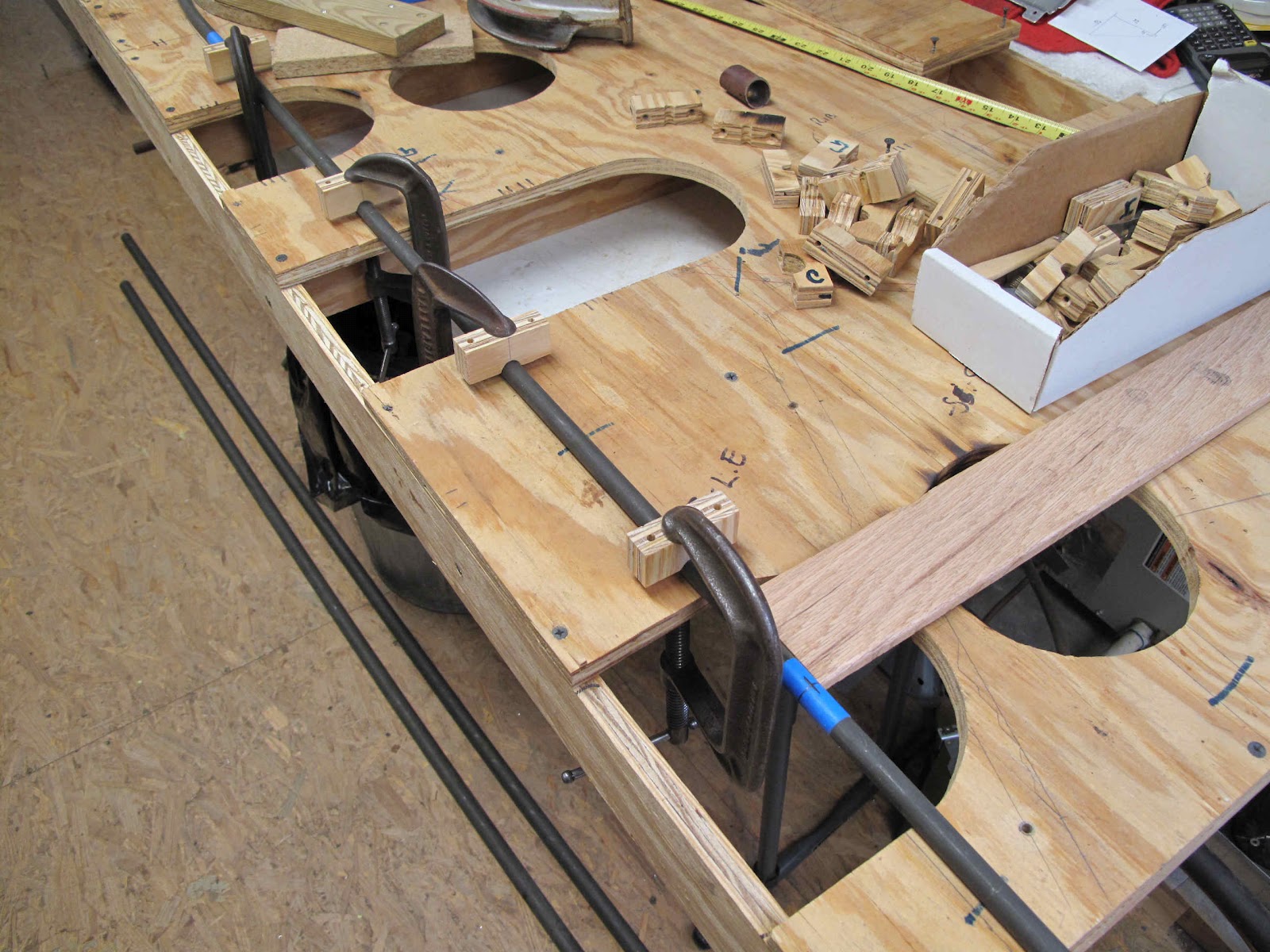
I made this piece of tubing 14'-6" long.  That's longer than needed but I needed enough extra at each end to be able to easily form the bends.  I think you could still do this with a piece 14'-0" long.  I started with the center of the tube (mark on blue tape) at the center of the stabilizer.  The blocks clamping the tube to the lines on the jig are the standoff blocks, turned upside down, I made for holding the tubes in place.  The blocks were made so the centers of the spars and leading edge are on the same plane, far enough from the board so the bottom ribs can fit under the spars.
 I used the same curved board I made for bending the trailing edge on the elevators and clamped it to the jig to form the bends at the tips.  I found it made a nice smooth curve by moving the board in about 1" increments.  In 2" increments you can see straight sections between the bends.
 I could have used more holes in the jig to hold the tube in place as the bend progressed.


As an alternative I clamped some blocks to hold the tube from over bending as I moved along the tube.

 At the end of the bend I had about 8" of tubing to cut off at the back of the spar (blue tape).
 The second bend was made with the same process.  The trick was to line up the first bend, dangling past the end of the board, with the surface of the board. By clamping the jig to the table so it would stand on edge I positioned the bent end parallel to the board.  It took several tries because the clamp needs to be exactly over the tube as you tighten it or the block rolls and the tube rolls with it.
 In the end both ends are bent and lined up.
The next step is to make the spar tubes.

No comments:

Post a Comment